LIDAR optical scanner system
a scanning system and optical scanner technology, applied in the field of timeofflight distance measurement, can solve the problems of inefficient use of scanning time, power consumption, mechanical scanning field, etc., and achieve the effect of reducing system complexity
- Summary
- Abstract
- Description
- Claims
- Application Information
AI Technical Summary
Benefits of technology
Problems solved by technology
Method used
Image
Examples
Embodiment Construction
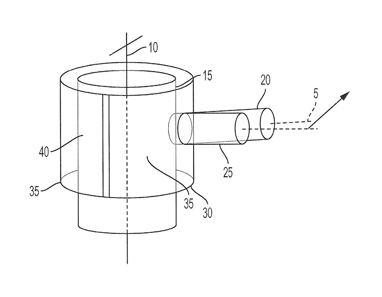
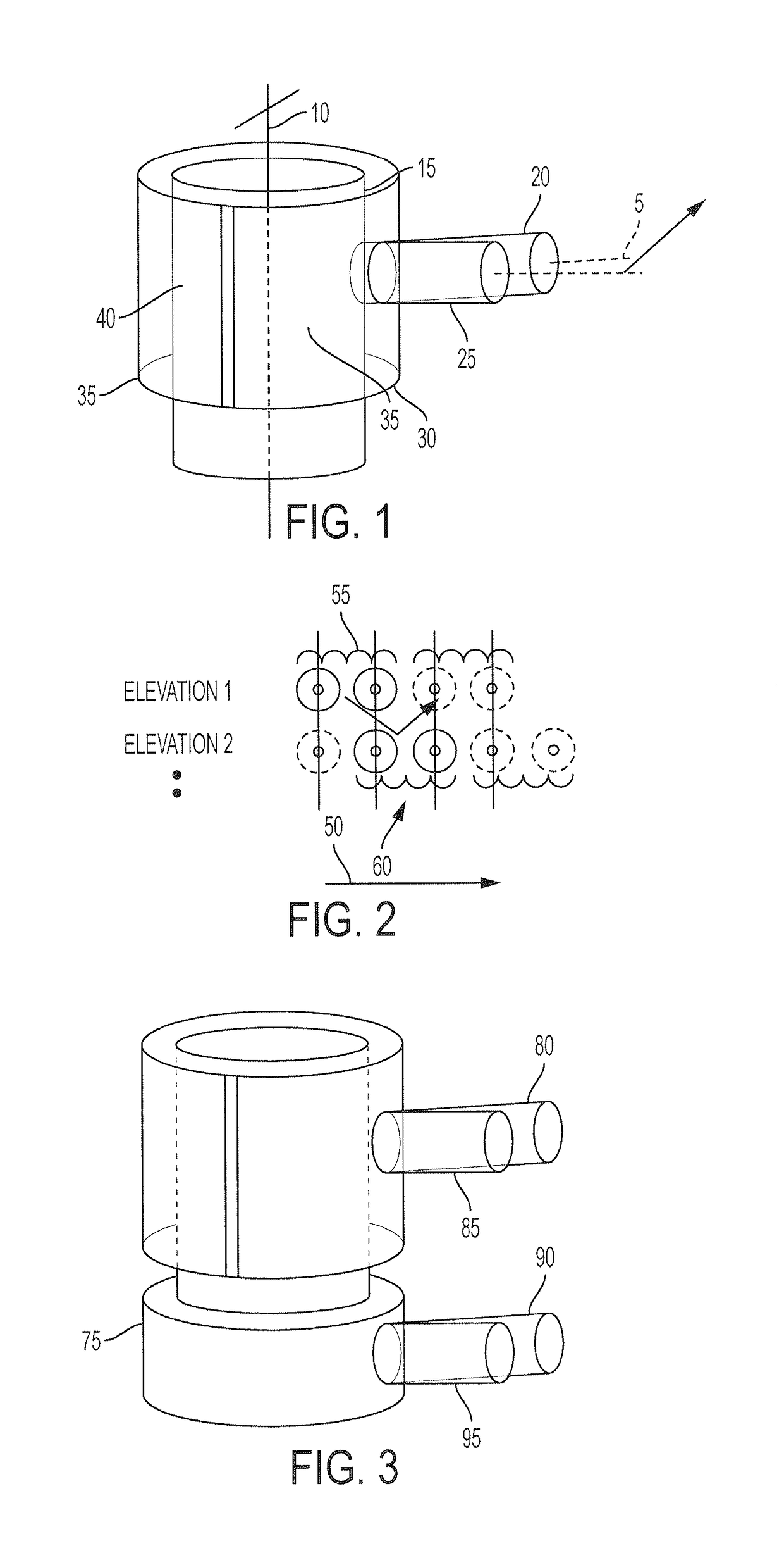
[0048]FIG. 1 illustrates a generic embodiment of a cylindrical shaped optical scanner receiver with external beam deflector. Inter housing 15, is shown with a central-axis 10. Two optical receive fields labeled 20 and 25 are displaced in azimuth in order to provide a look-ahead function to fill in coverage gaps resulting when external scanner component 30, selects alternating regions of elevation. Elevation deflection produced from regions 35 and 40 may be constructed using diffractive or refractive optics or in an alternate embodiment by an opaque mask used selectively block a range of elevation coverage. Although two separate elevation selection levels are shown, any number of elevation regions may be implemented based on the circumference of the scanner and the number of elevation scans per rotation.
[0049]FIG. 2 illustrates receiver field-of view coverage projected onto a plane due continuous lateral motion of the receiver optical axis. Two scanner elevations are illustrated alon...
PUM
 Abstract
Description
Claims
Application Information
 - R&D
- Intellectual Property
- Life Sciences
- Materials
- Tech Scout
- Unparalleled Data Quality
- Higher Quality Content
- 60% Fewer Hallucinations
Browse by: Latest US Patents, China's latest patents, Technical Efficacy Thesaurus, Application Domain, Technology Topic, Popular Technical Reports.
© 2025 PatSnap. All rights reserved.Legal|Privacy policy|Modern Slavery Act Transparency Statement|Sitemap|About US| Contact US: help@patsnap.com


