Switching power supply circuit and power factor correction circuit

a technology of power factor and power supply circuit, which is applied in the direction of energy industry, electrical energy, and power electronics conversion efficiency, can solve the problems of power factor worsening, power factor decreasing, phase deviating, etc., and achieves a high phase angle portion and a weakening power factor

Active Publication Date: 2017-05-23
FUJI ELECTRIC CO LTD
View PDF12 Cites 6 Cited by
  • Summary
  • Abstract
  • Description
  • Claims
  • Application Information

AI Technical Summary

Benefits of technology

[0066]The switching power supply circuit and power factor correction circuit of the heretofore described configuration have an advantage in that current waveform distortion and worsening power factor due to peak current increasing under continuous conduction control in a high phase angle portion can be reduced by masking a switch to continuous conduction control in a high phase angle portion of the alternating current input waveform.

Problems solved by technology

A rectifier circuit has a problem in that current flows into a smoothing capacitor connected to a latter stage of the rectifier circuit only when the input voltage reaches the vicinity of a peak exceeding the voltage of the smoothing capacitor, because of which a high frequency current component is generated, forming a high frequency noise source, and the power factor decreases.
However, a switching power supply is such that the current phase deviates from the voltage phase due to load factors other than resistance, such as a capacitor or choke coil.
Therefore, the critical conduction control method is characterized by being used in a power factor correction circuit of a switching power supply circuit with low power consumption in the region of, for example, 250 watts (W) or less, but not being appropriate to a power factor correction circuit of a switching power supply circuit of a larger capacity.
Furthermore, the power factor correction circuit restricts the generation of harmful electro-magnetic interference (EMI) and high frequency current or voltage that leads to instrument destruction.
As a result of this, there is a problem in that the current waveform distorts from a sine waveform to a waveform with a high peak with respect to the sine waveform of the alternating current input voltage, because of which the power factor worsens.

Method used


Image

  • Switching power supply circuit and power factor correction circuit
  • Switching power supply circuit and power factor correction circuit
  • Switching power supply circuit and power factor correction circuit

Examples


Embodiment Construction

[0081]Hereafter, referring to the drawings, a detailed description will be given of an embodiment of the disclosure.

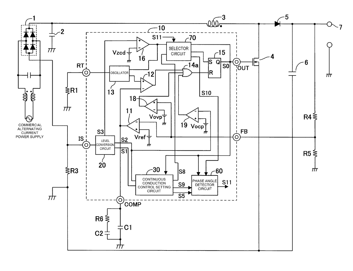
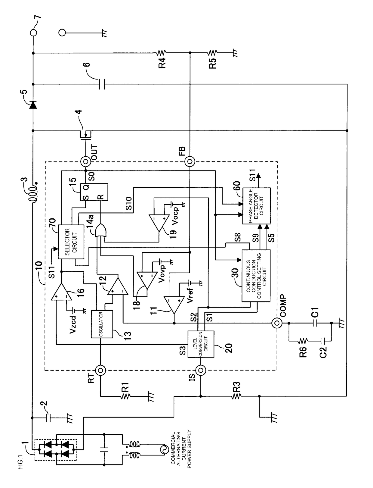
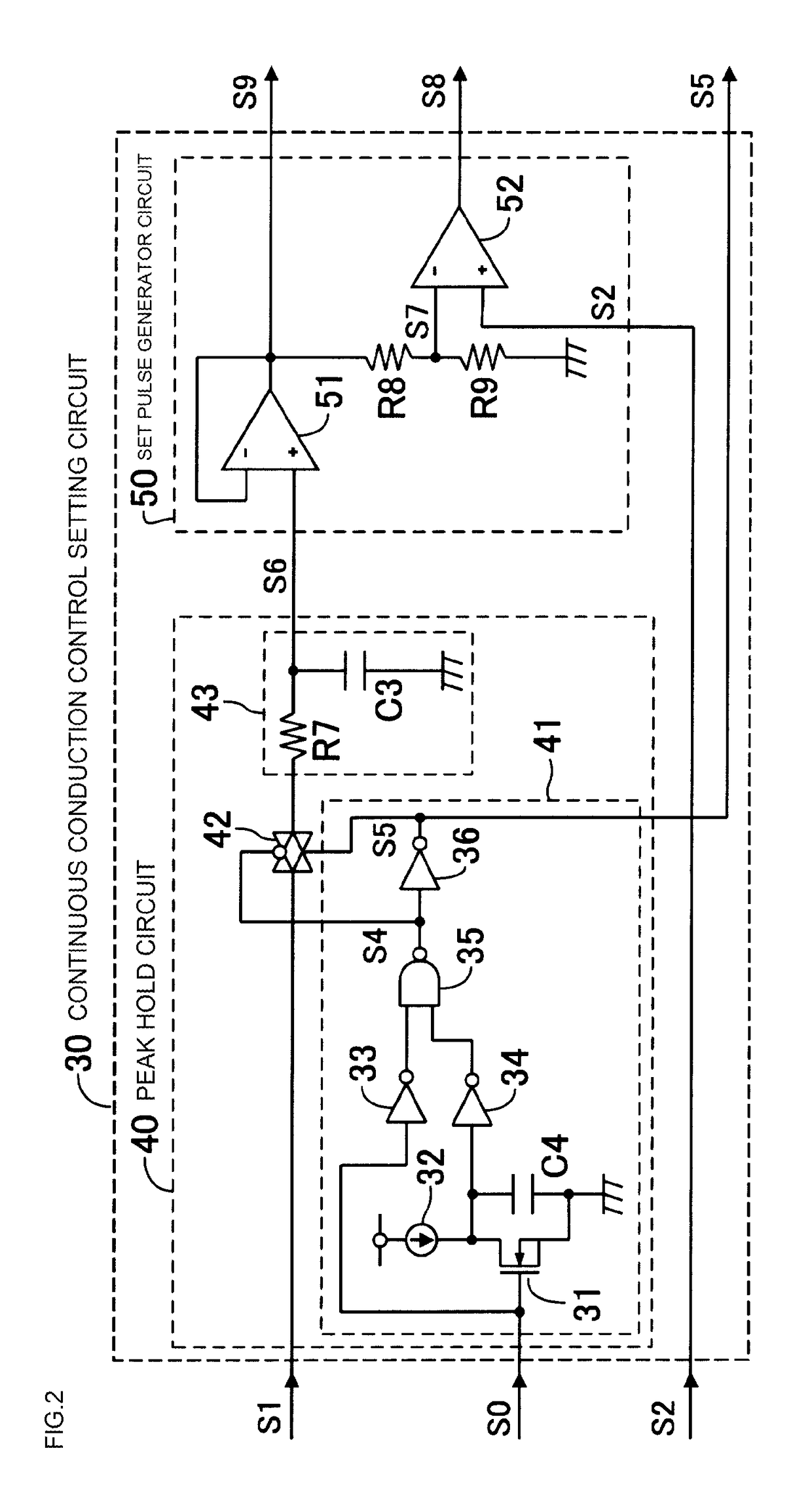
[0082]FIG. 1 is a circuit diagram showing a switching power supply circuit according to an embodiment of the disclosure, while FIG. 2 is a circuit diagram showing a configuration example of a continuous conduction control setting circuit. Hereafter, the same reference signs will be used for components, terminal names, signal names, and the like, corresponding to circuits shown in FIG. 8 and FIG. 9, which are existing examples, and redundant descriptions will be omitted.

[0083]A switching power supply circuit shown in FIG. 1 has a full-wave rectifier circuit 1, which full-wave rectifies an alternating current power supply to obtain a pulsating output, and an inductor 3 connected to the full-wave rectifier circuit 1, and supplies direct current output voltage of a predetermined size from the alternating current power supply to a load. In the switching power supply circuit...


PUM


Abstract

A switching power supply circuit including a phase angle detector circuit detecting a phase angle specified in advance based on a peak hold signal, a continuous conduction control setting circuit holding a voltage value corresponding to a peak current value of an inductor current detection voltage in every switching cycle and during a one-shot pulse when the peak is held and outputting a signal at the point of detection to determine to enable or disable a second set pulse set by the continuous conduction control setting circuit. When the second set pulse is disabled, a selector circuit carries out control using critical conduction control to turn on a switching element using a ZCD comparator detecting that the inductor current has reached zero, because of which the peak current does not increase.

Description

CROSS-REFERENCE TO RELATED APPLICATIONS[0001]This application claims benefit of foreign priority to Japanese Application 2015-028520 filed on Feb. 17, 2015, the disclosure of which is incorporated herein by reference.BACKGROUND[0002]1. Field[0003]The present disclosure relates to a switching power supply circuit and power factor correction circuit that convert an alternating current input voltage to a predetermined direct current output voltage and supply the output voltage to a load, and in particular, relates to a switching power supply circuit and power factor correction circuit such that switching can be carried out between a critical conduction control method and a continuous conduction control method.[0004]2. Related Art[0005]A switching power supply circuit is used in many electronic instruments to which a commercial alternating current power supply (100V to 240V AC) is supplied in order to obtain a direct current power supply that drives an internal electronic circuit. There...

Claims


Application Information

Patent Timeline
Patent Type & Authority Patents(United States)
IPC IPC(8): H02M1/42H02M7/217H02M1/08H02M1/00
CPCH02M1/4225H02M1/083H02M2001/0032Y02B70/126Y02B70/16Y02P80/112H02M1/4266H02M3/1563H02M7/219Y02B70/10Y02P80/10H02M1/0032
Inventor MARUYAMA, HIROSHI
Owner FUJI ELECTRIC CO LTD
Why Eureka
Try Eureka