Wire harness routing structure

a wire harness and routing structure technology, applied in the direction of wing accessories, doors, cable arrangements between relatively moving parts, etc., can solve the problems of reducing the durability of flexible conductors, the difficulty of maintaining the routing path formed into a u-shape, etc., to prevent the breakage of the wire harness, increase the number of circuits, and reduce the rigidity of the wire harness

Active Publication Date: 2017-06-06
YAZAKI CORP
View PDF5 Cites 6 Cited by
  • Summary
  • Abstract
  • Description
  • Claims
  • Application Information

AI Technical Summary

Benefits of technology

[0007]In view of the above-described drawbacks, it is an object of the present invention to provide a wire harness routing structure which can prevent breaking of a wire harness, which can improve visual quality by invisibly-arranging the wire harness, which can improve bending durability of the wire harness with respect to sliding action of a slide door, and which can be used for the wire harness for multicircuit.
[0015]According to the inventions described in the first to eighth aspects, all the time during the operation of the slide door from the fully-opened state to the fully-closed state, the wire harness is positioned along the slide door rail, or positioned in the groove of the slide door rail, or stored in the case. Thus, a passenger cannot see or contact with the wire harness, thereby preventing the passenger from stepping on the wire harness and preventing the breakage of the wire harness. Furthermore, if the rigidity of the wire harness is increased due to an increase in number of circuits, the trajectory of the wire harness can be reliably restricted by the slide door rail and the case, thereby addressing the increase in number of circuits. Furthermore, the wire harness is prevented from being applied with unnecessary tension, thereby improving the bending durability.

Problems solved by technology

As a result, it is difficult to maintain the routing path which is formed into a U-shape for space saving, for example.
Moreover, the routing path of the flexible conductors may extend outward causing the flexible conductors to interfere with other components, or the flexible conductors may be bent locally causing a decrease in durability of the flexible conductors.Patent Literature 1: Japanese Patent Application Publication No. 2000-177508

Method used


Image

  • Wire harness routing structure
  • Wire harness routing structure
  • Wire harness routing structure

Examples


first embodiment

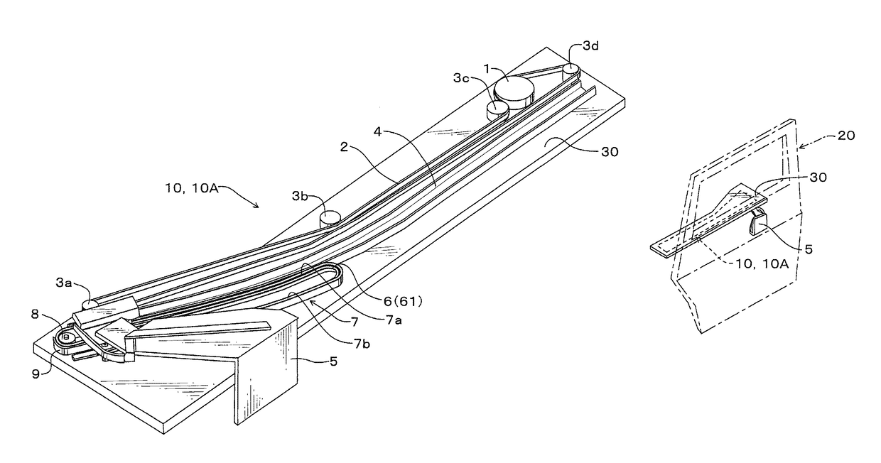
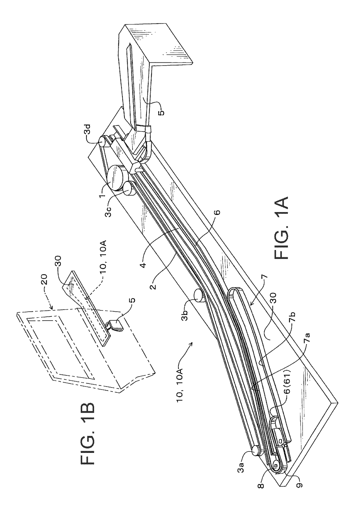
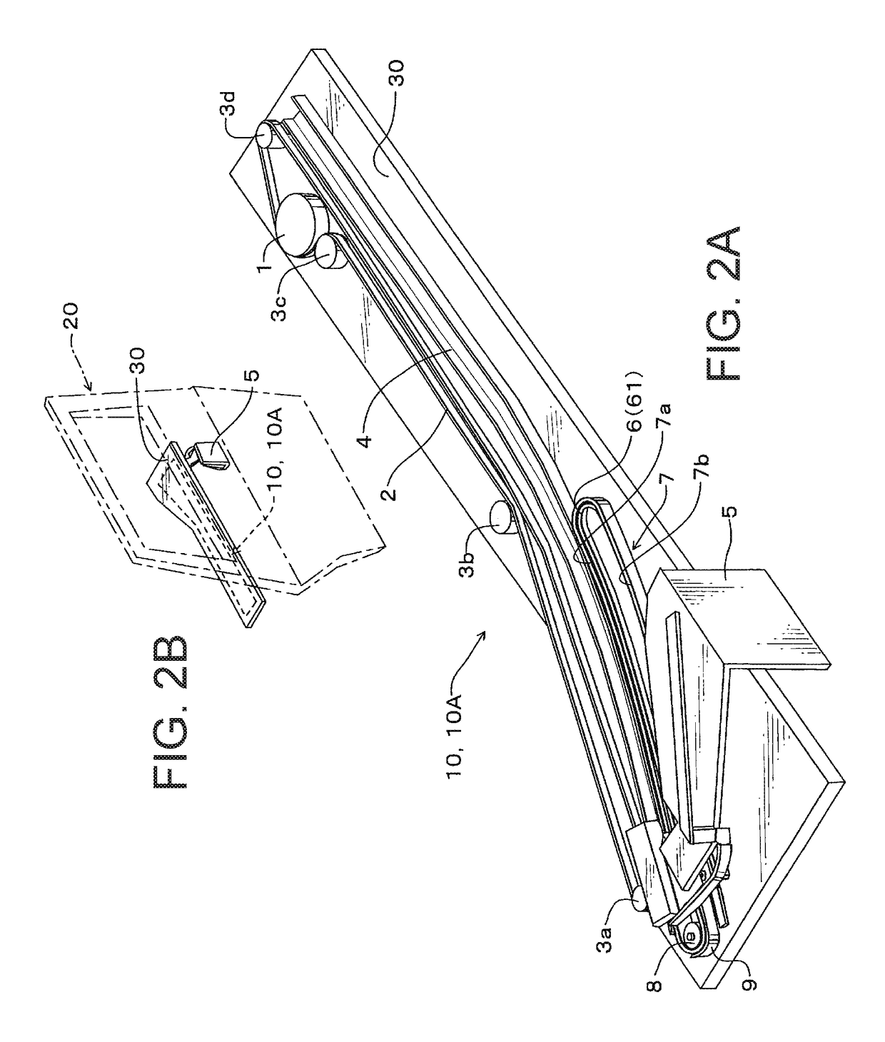
[0029]A power supply device 10 is employed in a slide mechanism 10A for opening and closing a slide door 20 of a vehicle. The power supply device 10 and the slide mechanism 10A are mounted to an under side (lower side) of a base 30 as “base member” provided to an under side of a door step of the vehicle. The door step (i.e., under side of the door step) itself may be the base 30 as “base member”. The slide mechanism 10A includes the slide door 20 arranged to slide with respect to the base 30, a sprocket 1 which outputs rotational power by a rotational power source, a drive belt 2 which extends in a slide direction of the slide door 20 and transmits the rotational power from the rotational power source to the slide door 20 as slide force, a plurality of pulleys 3 (3a, 3b, 3c, 3d) configured to extend the drive belt 2 throughout the device, a slide door rail 4 which extends in a front-rear direction of the vehicle and which is slightly curved, and a slide door arm 5 connecting the sl...

seventh embodiment

[0049]In this seventh embodiment also, the wire harness 6 is disposed in the groove of the slide door rail 4 or stored between the side surface 4b of the slide door rail 4 and the wall members 14a, 14b, 14c, 14d during the operation of the slide door 20 from the fully-opened state shown to the fully-closed state of the slide door 20. Thus, a passenger cannot see or contact with the wire harness 6. In addition, the slide door rail 4 is located at under side of the base 30, thereby preventing the passenger from stepping on the wire harness 6.

[0050]FIGS. 11A and 11B show perspective view of a power supply device and a slide mechanism employing a wire harness routing structure according to an eighth embodiment, in which a slide door is in a fully-opened state. FIGS. 12A and 12B show perspective view of the power supply device and the slide mechanism employing the wire harness routing structure according to the eighth embodiment, in which the slide door is in a fully-closed state. This e...


PUM


Abstract

Provided is a power supply device for supplying power to a slide door via a wire harness, in which the wire harness is arranged invisible, which can improve bending durability of the wire harness with respect to sliding action of the slide door, and which can be used for the wire harness for multicircuit. In the power supply device, the wire harness is routed from a slide door arm through inside a slide door rail, through a roller and a guide plate and to a case. All the time during the operation of the slide door from a fully-opened state to a fully-closed state of the slide door, the wire harness is stored in a groove of the slide door rail or in the case.

Description

CROSS REFERENCE TO RELATED APPLICATIONS[0001]This application is on the basis of Japanese Patent Application No. 2016-012490, the contents of which are hereby incorporated by reference.TECHNICAL FIELD[0002]The present invention relates to a wire harness routing structure for a power supply system supplying power to a sliding door and such of a vehicle via a wire harness.BACKGROUND ART[0003]A slide door used for a vehicle is embedded with electric components such as a power window motor. To supply power to these electric components, it is necessary to provide a wire harness (a wire) routed from a vehicle body to the slide door, such that this wire harness can follow the opening and closing operation of the slide door.[0004]Meanwhile, Japanese Patent Application Publication No. 2000-177508 (hereinafter, “Patent Literature 1”), for example, discloses a mechanism for continuously supplying power including a wire harness for a slide door which is arranged in an invisible manner. Specific...

Claims


Application Information

Patent Timeline
Patent Type & Authority Patents(United States)
IPC IPC(8): H02G3/04E05D15/28B60J5/06B60R16/027H02G11/00E05F15/646
CPCE05D15/28B60J5/06B60R16/027E05F15/646H02G11/00E05Y2400/654E05Y2900/531
Inventor TSUBAKI, AKIRA
Owner YAZAKI CORP
Why Eureka
Try Eureka