Method of testing waterproof performance of radiological imaging apparatus, and radiological imaging apparatus
a radiological imaging and waterproof performance technology, applied in the direction of fluid tightness measurement, instruments, applications, etc., can solve the problems of long time period, inability to easily test the waterproof performance of the radiological imaging apparatus, and inability to meet the needs of the patient, so as to achieve the effect of quick testing in a relatively short period of tim
- Summary
- Abstract
- Description
- Claims
- Application Information
AI Technical Summary
Benefits of technology
Problems solved by technology
Method used
Image
Examples
first embodiment
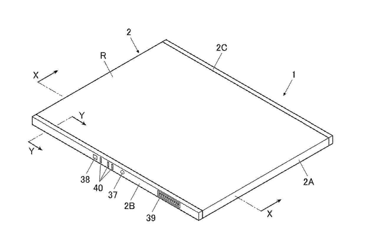
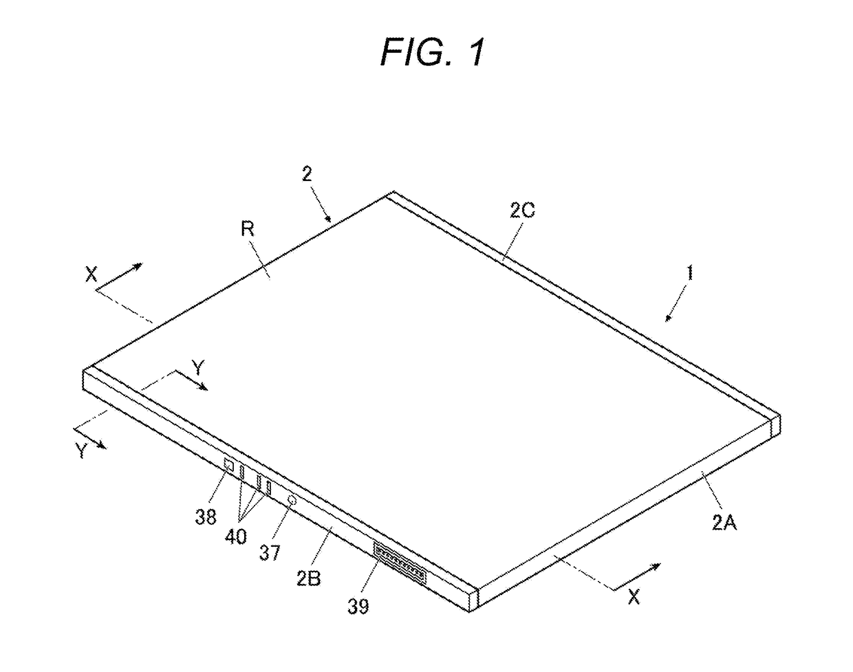
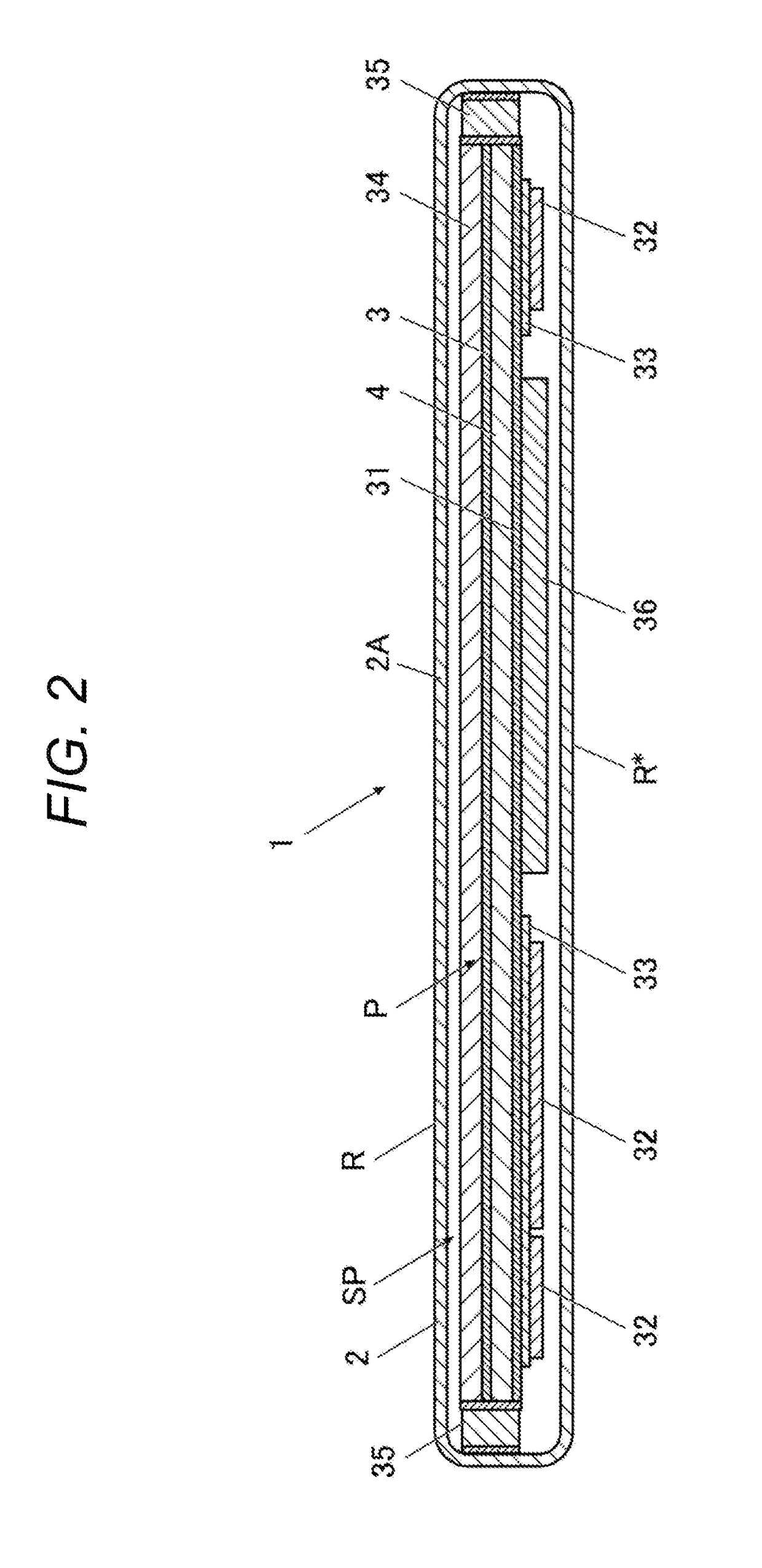
[0056]A first embodiment concerns a case where an air pressure measuring unit such as an air pressure sensor that measures the air pressure inside the housing 2 is provided in the housing 2, and a check is made to determine whether the waterproof performance of the radiological imaging apparatus 1 is normal based on the air pressure inside the housing 2 measured by the air pressure measuring unit, as by the waterproof performance testing method disclosed in JP 2009-121965 A.
[0057]By the waterproof performance testing method disclosed in JP 2009-121965 A, a testing device for changing the atmospheric pressure outside the apparatus is required. In this embodiment, however, such a testing device is unnecessary. Further, by the waterproof performance testing method disclosed in JP 2009-121965 A, the atmospheric pressure outside the apparatus is changed. In this embodiment, however, the atmospheric pressure outside the housing 2 of the radiological imaging apparatus 1 is not changed, as ...
second embodiment
[0103]In the above described first embodiment, the load application step (step S1 in FIG. 5B) and the air pressure measurement step (step S2) are carried out while the vent hole H (see FIG. 4) is left open. However, these steps can be carried out, with the vent hole H being closed.
[0104]In this case, when the housing 2 of the radiological imaging apparatus 1 is pressed with a hand or a weight is placed on the housing 2 to apply a load to the housing 2, the air in the housing 2 does not flow out as long as the waterproof performance is normal. If the load application is continued, the air pressure P in the housing 2 shoots up when the load application to the housing 2 is started (time t0) and increases to the maximum value Pmax of the air pressure P (time t1), as shown in FIGS. 6A and 6B, and FIGS. 7A and 7B. After that, however, the air pressure P in the housing 2 is maintained almost constant as indicated by a dot-and-dash line γ in FIG. 8.
[0105]In a case where the waterproof perfo...
third embodiment
[0109]In the above described first and second embodiments, the housing 2 of the radiological imaging apparatus 1 is pressed with a hand, or a weight is placed on the housing 2, so as to continue load application to the housing 2 in the load application step (step S1 in FIG. 5B). Although a load is applied to the housing 2 of the radiological imaging apparatus 1 to cause the air to flow out of the housing 2 through the vent hole H in the load application step in this embodiment, the load application to the housing2 of the radiological imaging apparatus 1 may be stopped, and the air pressure P in the housing 2 that continues to increase thereafter may be measured with the air pressure measuring unit 50 in the air pressure measurement step (step S2).
[0110]In the description below, the case where a load is applied to the portion 51 shown in FIG. 5A will not be explained, but a load can also be applied to the portion 51 in this embodiment.
[0111]In this case, when load application to the ...
PUM
 Abstract
Description
Claims
Application Information
 - R&D
- Intellectual Property
- Life Sciences
- Materials
- Tech Scout
- Unparalleled Data Quality
- Higher Quality Content
- 60% Fewer Hallucinations
Browse by: Latest US Patents, China's latest patents, Technical Efficacy Thesaurus, Application Domain, Technology Topic, Popular Technical Reports.
© 2025 PatSnap. All rights reserved.Legal|Privacy policy|Modern Slavery Act Transparency Statement|Sitemap|About US| Contact US: help@patsnap.com


