Transmission assembly for use in an exoskeleton apparatus

a technology of exoskeleton and assembly, which is applied in the field of exoskeleton apparatuses, can solve the problems of manual and laborious rehabilitation, serious health complications, etc., and achieve the effects of reducing the stress on the user's knee joint, and reducing the stress on the lower leg portion

Active Publication Date: 2017-06-13
BIONIK LAB
View PDF148 Cites 8 Cited by
  • Summary
  • Abstract
  • Description
  • Claims
  • Application Information

AI Technical Summary

Benefits of technology

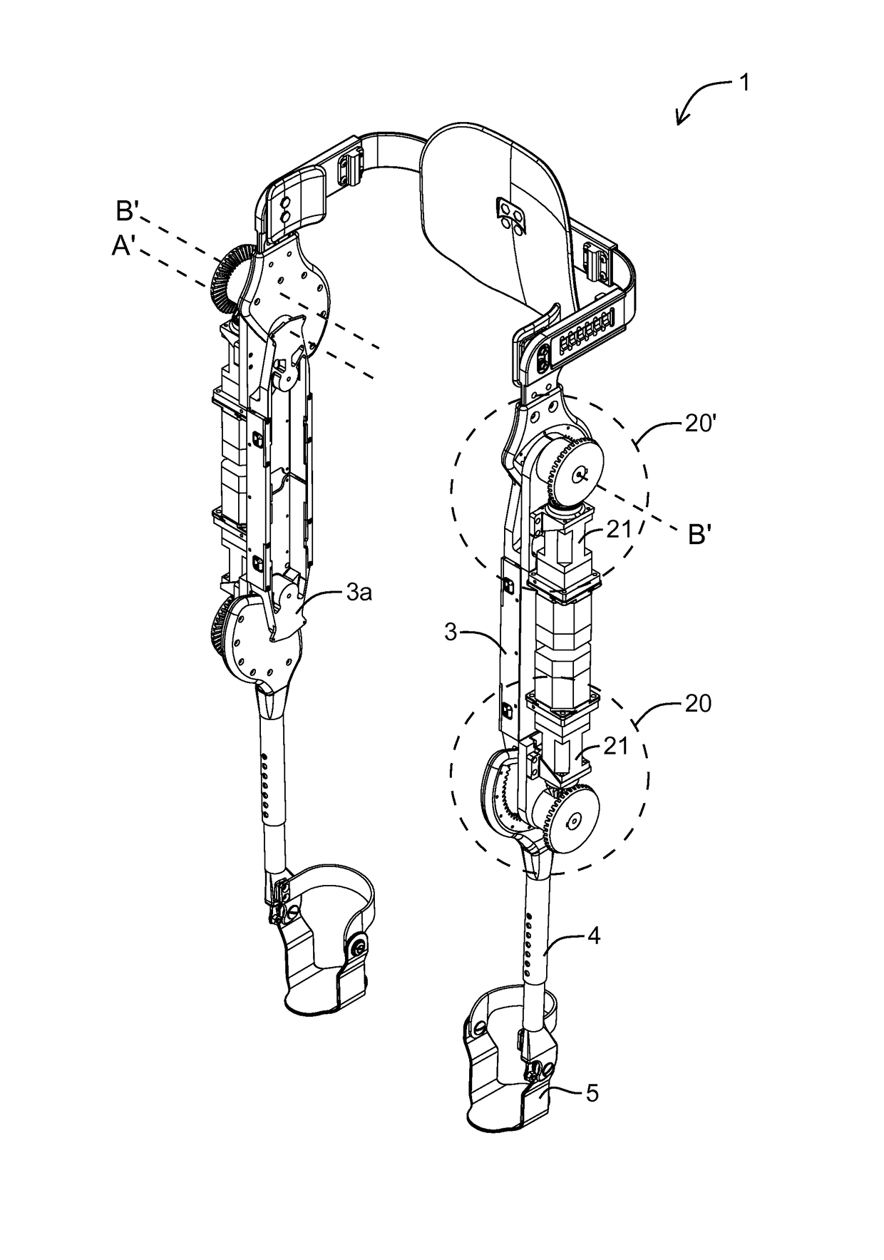
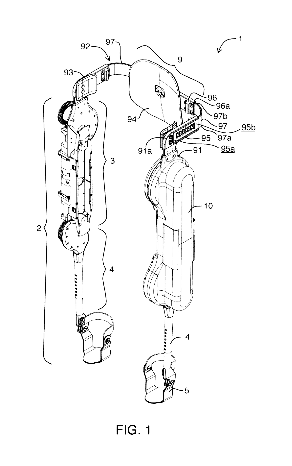
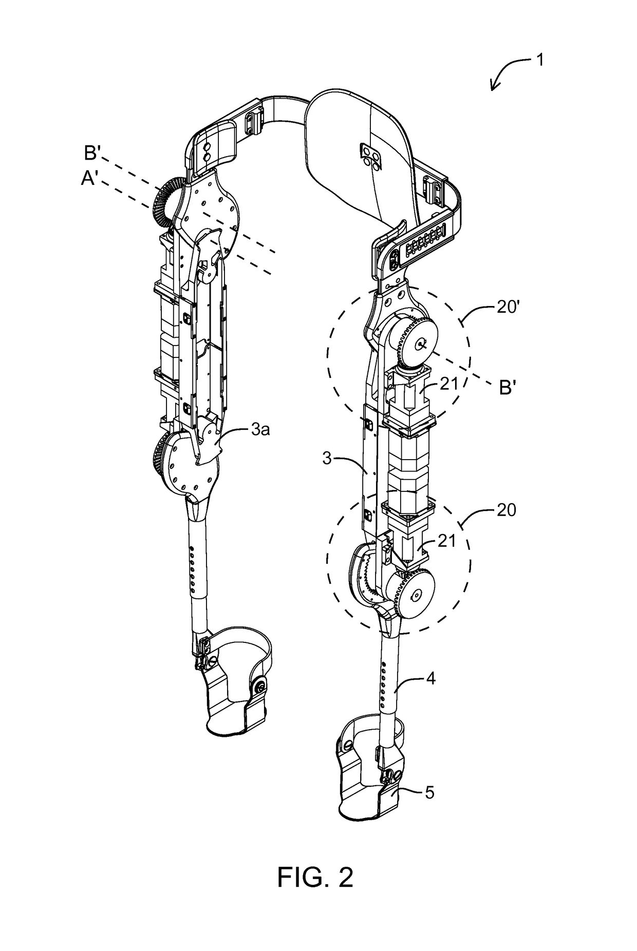
[0016]One advantage of the transmission construction is that the drive motors for the knee joint may be provided on the upper leg portion, since the upper leg portion is anatomically better suited to support the additional weight as compared to the lower leg portion. More particularly, if a drive motor were provided on the lower leg portion below the knee, the lower leg portion would have a higher mass moment of inertia. This weight reduction reduces stress on the user's knee joint.
[0061]In accordance with another aspect, which may be used by itself or with any one or more other aspects, an air bladder strap design may be used. The air bladder strap may be inflated to a predetermined pressure that effectively secures the strap against the user's limb or body. While in use, the inflatable bladder distributes pressure against the limb or body, reducing pressure points and the potential for injury.

Problems solved by technology

Aside from the obvious health difficulties, such as lack of mobility, there are numerous secondary health issues associated with paraplegia.
Also, secondary conditions do not exist in isolation but have the potential to exacerbate each other, which can lead to serious health complications.
Currently, rehabilitation is a manual and laborious process.
However, once the session is complete, the patient typically returns to a wheelchair and receives no further exercise until the next rehabilitation session.

Method used


Image

  • Transmission assembly for use in an exoskeleton apparatus
  • Transmission assembly for use in an exoskeleton apparatus
  • Transmission assembly for use in an exoskeleton apparatus

Examples


Embodiment Construction

[0096]Various apparatuses or processes will be described below to provide an example of an embodiment of each claimed invention. No embodiment described below limits any claimed invention and any claimed invention may cover processes or apparatuses that differ from those described below. The claimed inventions are not limited to apparatuses or processes having all of the features of any one apparatus or process described below or to features common to multiple or all of the apparatuses described below. It is possible that an apparatus or process described below is not an embodiment of any claimed invention. Any invention disclosed in an apparatus or process described below that is not claimed in this document may be the subject matter of another protective instrument, for example, a continuing patent application, and the applicants, inventors or owners do not intend to abandon, disclaim or dedicate to the public any such invention by its disclosure in this document.

[0097]The describ...


PUM


Abstract

An exoskeleton for a limb of a user wherein the limb has an upper portion connected to the body of a user and a lower limb portion is provided. The exoskeleton comprises a drive force transmission mechanism drivingly connecting a drive motor having an output axle aligned with the upper limb portion to one of the body portion and the lower limb portion. The drive force transmission mechanism comprises a first gear provided on an upper end of the lower limb portion or on the body portion and a first transfer member extending transverse to the motor axis.

Description

FIELD[0001]This specification relates to an exoskeleton apparatus. In a preferred embodiment, this specification relates to a transmission assembly for an exoskeleton apparatus. Preferably, the transmission assembly imparts rotational motion to a joint from a drive motor that is laterally mounted and oriented generally parallel to the portions of a body that meet at the joint.INTRODUCTION[0002]The following is not an admission that anything discussed below is part of the prior art or part of the common general knowledge of a person skilled in the art.[0003]Spinal cord injury is one of the primary causes of paralysis. Spinal cord injuries can be of varying severity, ranging from high C level injuries to Low S level injuries. Spinal cord injuries may result in paraplegia—the loss of movement or feeling in the lower limbs—or even quadriplegia—the loss of movement or feeling in both the lower and upper limbs.[0004]A person with complete or partial paraplegia is typically restricted to a...

Claims


Application Information

Patent Timeline
Patent Type & Authority Patents(United States)
IPC IPC(8): A61H3/00A61H1/02
CPCA61H3/00A61H1/024A61H1/0244A61H1/0277A61H1/0281A61H2201/0103A61H2201/1463A61H2201/165A61H2201/5007A61H2201/5071
Inventor CAIRES, THIAGOPRYWATA, MICHAL
Owner BIONIK LAB
Why Eureka
Try Eureka