Eccentric shaft assembly having fixed and movable eccentric masses

a technology of eccentric shaft and eccentric mass, which is applied in the direction of controlling members, soil preservation, controlled members, etc., can solve the problems of eccentric shaft unnecessarily power and energy consumption, in relation, and inability to achieve optimal results

a technology of eccentric shaft and eccentric mass, which is applied in the direction of controlling members, soil preservation, controlled members, etc., can solve the problems of eccentric shaft unnecessarily power and energy consumption, in relation, and inability to achieve optimal results

US20150139731A1Active Publication Date: 2015-05-21DYNAPAC COMPACTION EQUIP

Image

  • Eccentric shaft assembly having fixed and movable eccentric masses
  • Eccentric shaft assembly having fixed and movable eccentric masses
  • Eccentric shaft assembly having fixed and movable eccentric masses

Examples


Embodiment Construction

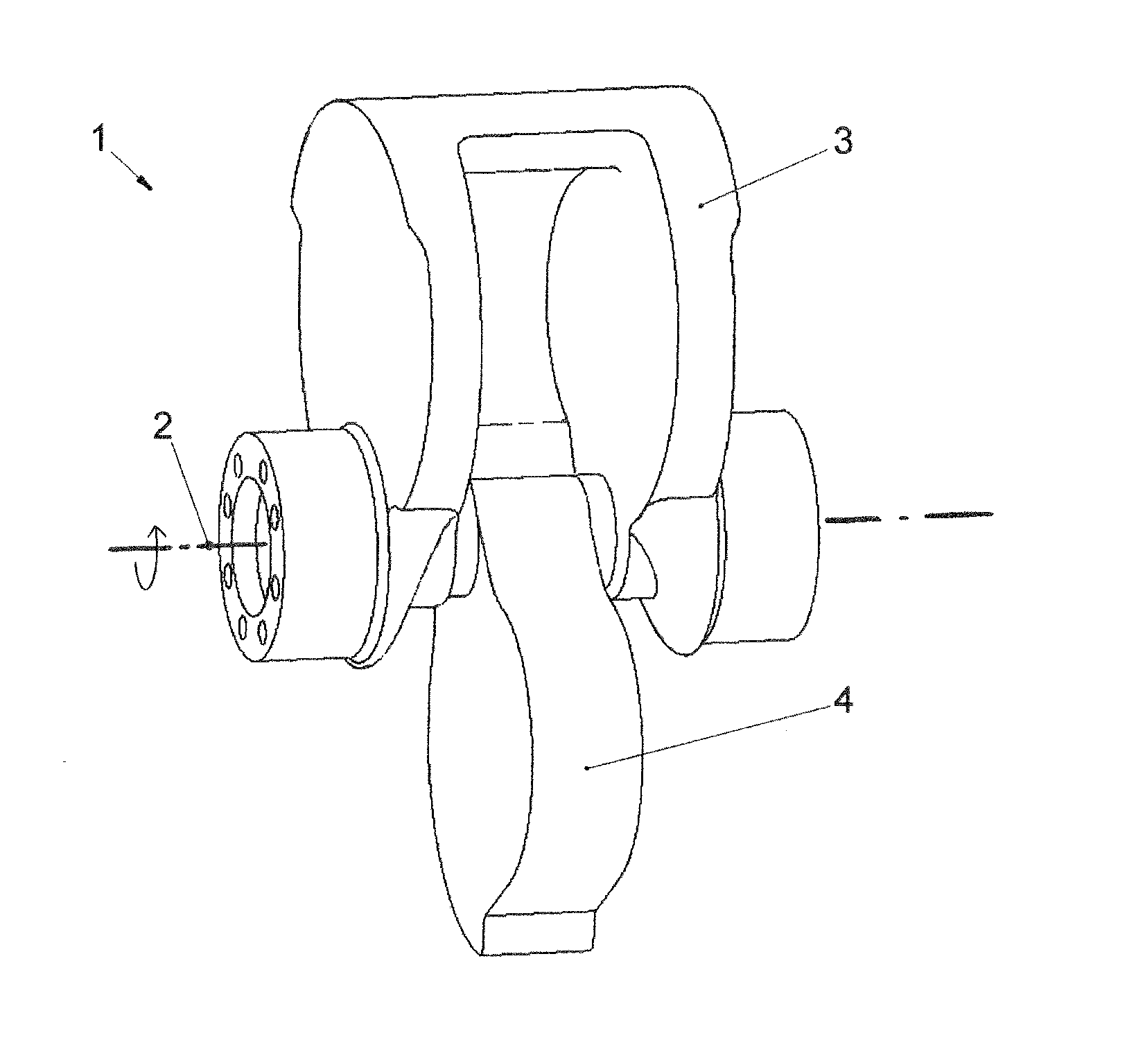
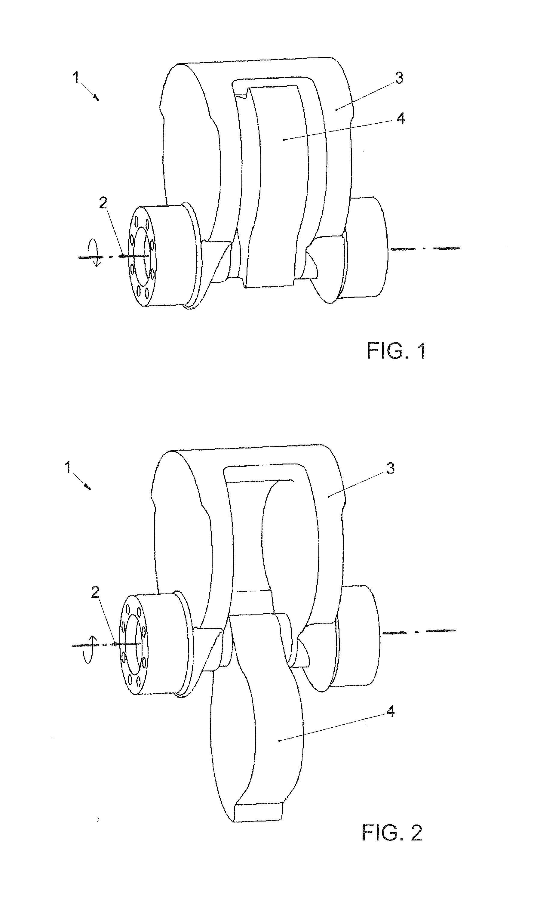
[0016]FIG. 1 shows an eccentric shaft 1 of dual-amplitude-type rotatable arranged about a rotational axis 2 in the drum of an asphalt roller (cf. FIG. 10). FIG. 1 shows an on-the-spot view of the eccentric shaft 1 when it is rotated in one of its rotation directions about the rotational axis 2. The rotation direction is clockwise and is illustrated by a curved arrow in the drawing. The eccentric shaft 1 incorporates a fixed eccentric mass 3 and a movable eccentric mass 4. The fixed eccentric mass 3 is configured as a cast component in nodular ductile iron. Both the shaft ends of the eccentric shaft 1 are connected to the fixed eccentric mass 3 and have machine finished surfaces for the bearings 12 (cf. FIG. 10) which makes the shaft 1 rotatable. The bearings are arranged in cassettes (14, 16) arranged in respective gable ends (18, 20) of the drum 22 as shown in FIG. 10.

[0017]The left hand end of the shaft is connected to a hydraulic motor 24 which rotates the shaft 1 about the rotat...


PUM


Abstract

An eccentric shaft for a compacting machine is rotatable about a rotational axis and includes a fixed and movable eccentric mass where the movable eccentric mass cooperates with the fixed eccentric mass in one of the directions of rotation of the eccentric shaft to partly balance the fixed eccentric mass in the other rotation direction of the eccentric shaft. At least one section of the fixed eccentric mass shows a maximal radial extension (UB) in relation to the rotational axis, limited by an arc-shaped curve, which extends to a circle shape, with the diameter (D) showing a distance (A), between the point (P) on the circle-shaped curve that is located closest to the point of intersection of the rotational axis and the section plane, and the point of intersection, from 0 up to 0.1(D).

Description

CROSS REFERENCE TO RELATED APPLICATION[0001]This application claims priority of Swedish patent application no. 1300711-7, filed Nov. 15, 2013, the entire content of which is incorporated herein by reference.FIELD OF THE INVENTION[0002]The invention is directed to a configuration of eccentric shafts of the dual amplitude type intended for use in compacting machines such as road rollers, for example. The eccentric shafts have a high eccentric moment in one rotation direction and a lower eccentric moment in the other rotation direction. The eccentric shafts include a fixed and movable eccentric mass. The movable eccentric mass is arranged to cooperate with the fixed eccentric mass in one rotation direction of the eccentric shaft and to partly balance the fixed eccentric mass in the other rotation direction of the eccentric shaft. The eccentric shafts are configured for start with low start torque. The latter characteristic contributes to reduce the fuel consumption of the compacting ma...

Claims


Application Information

Patent Timeline
21 May 2015
Publication
US20150139731A1
IPC
E02D3/074; E02D3/026; F16C3/18
CPC
E02D3/074; E02D3/026; F16C3/18; E01C19/286; E01C19/38; Y10T74/2111; E01C19/00
Inventors
PERSSON, ANDREAS; CHRISTENSEN, HANS