Programmable device, control method of device and information processing system

a programmable device and control method technology, applied in the direction of pulse technique, instruments, computation using denominational number representation, etc., can solve the problems of leaking power, occupying as much as approximately 50% of the total consumed energy of the chip, and unable to perform immediate restart operation from a pre-standby state, so as to achieve the effect of saving power and effectively reducing power consumption

Active Publication Date: 2011-01-04
PANASONIC CORP
View PDF11 Cites 25 Cited by
  • Summary
  • Abstract
  • Description
  • Claims
  • Application Information

AI Technical Summary

Benefits of technology

[0012]By including the above-described structure, the programmable device of the present invention can cutoff and restore power to core logic units not being used, without losing internal states of such core logic units, thereby enabling saving power by effectively reducing power consumed by unnecessary current leaks that occur due to constantly supplying power to the core logic unit.
[0013]Here, since the consumed power of the core logic unit is normally higher than the consumed power of a configuration memory unit by two digits, cutting off the power supply to the core logic unit alone reduces the consumed energy to approximately less than or equal to 1%.
[0014]Also, upon temporarily cutting off the power supply to both the core logic unit and the configuration memory, when again power is supplied and both are caused to operate, there is a need to sequentially read initial settings, etc. from an external storage device or the like to the configuration memory, and the reading takes time. By supplying power to the configuration memory as in the present invention, since it is not necessary to take time for reading initial settings, etc. from an external storage device or the like to the configuration memory as described above, it is possible to rapidly cut off and restore power, and reduce the time needed for processing for the device as a whole.

Problems solved by technology

When the device is made to be more high-speed and miniaturized, there is a problem of leaked power, which takes up as much as approximately 50% of the total consumed energy of a chip.
However, in the above-described technology, there is the following issue.
Therefore, restarting operation from a pre-standby state cannot be performed immediately.

Method used


Image

  • Programmable device, control method of device and information processing system
  • Programmable device, control method of device and information processing system
  • Programmable device, control method of device and information processing system

Examples


embodiment 1

1. Embodiment 1

1.1 Structure

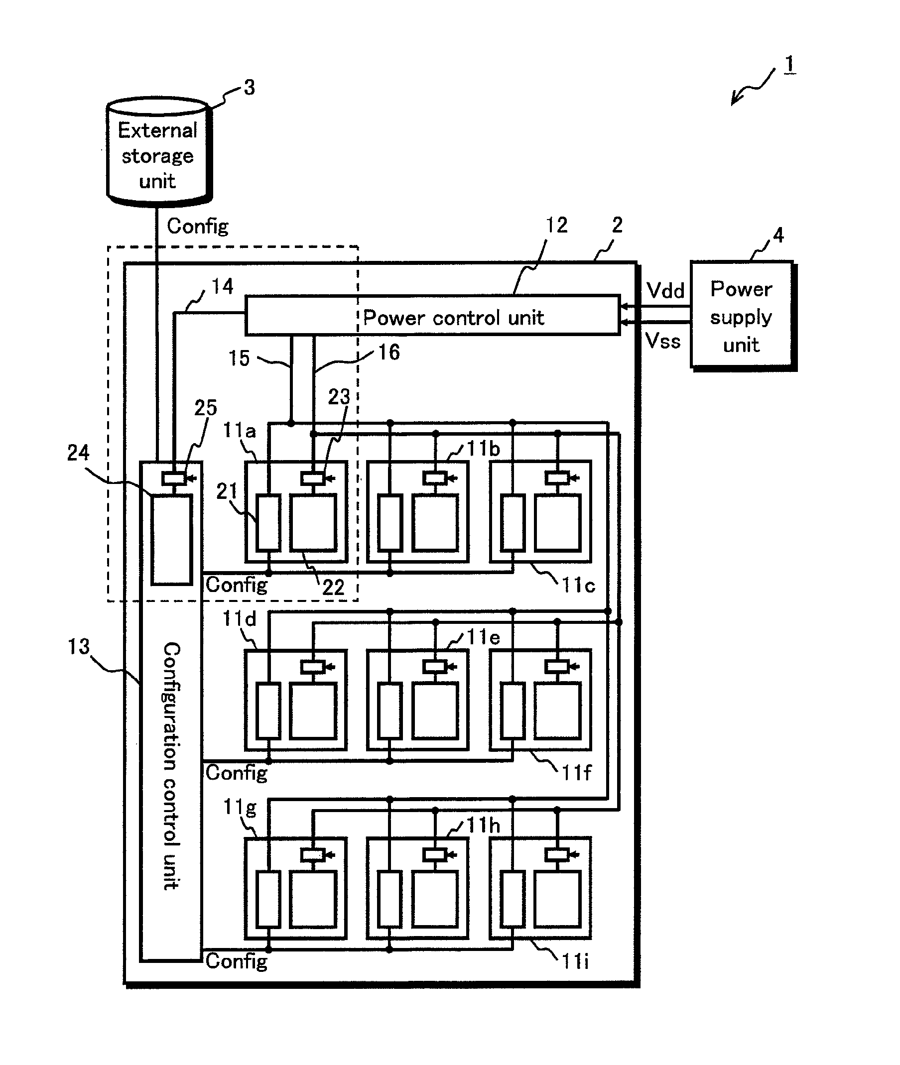
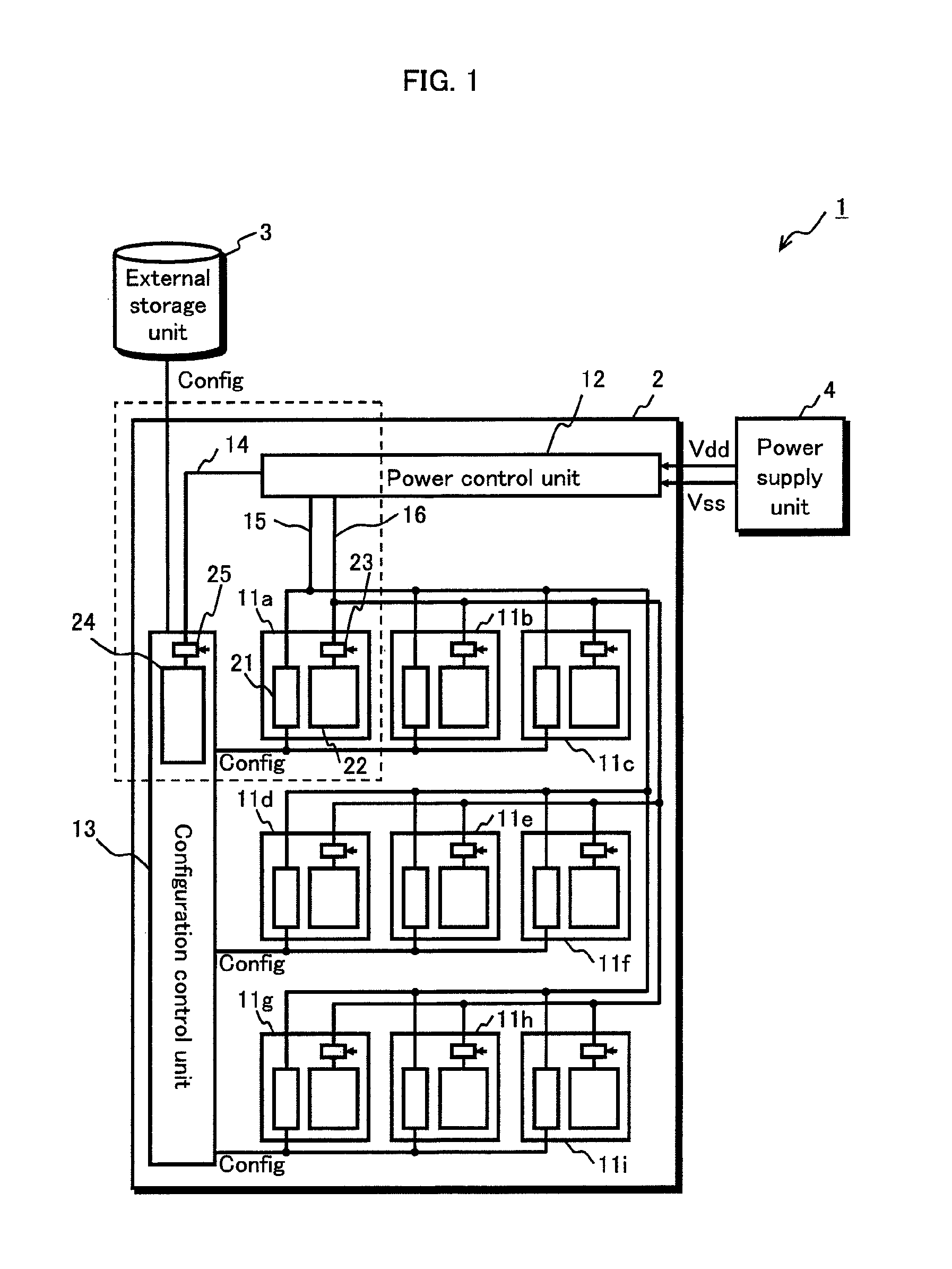
[0072]FIG. 1 shows a block diagram of a processing system 1 pertaining to the present embodiment.

[0073]The processing system 1 includes a programmable device 2, an external storage unit 3 for storing configuration information (Config) of circuits in the programmable device 2, and a power supply unit 4.

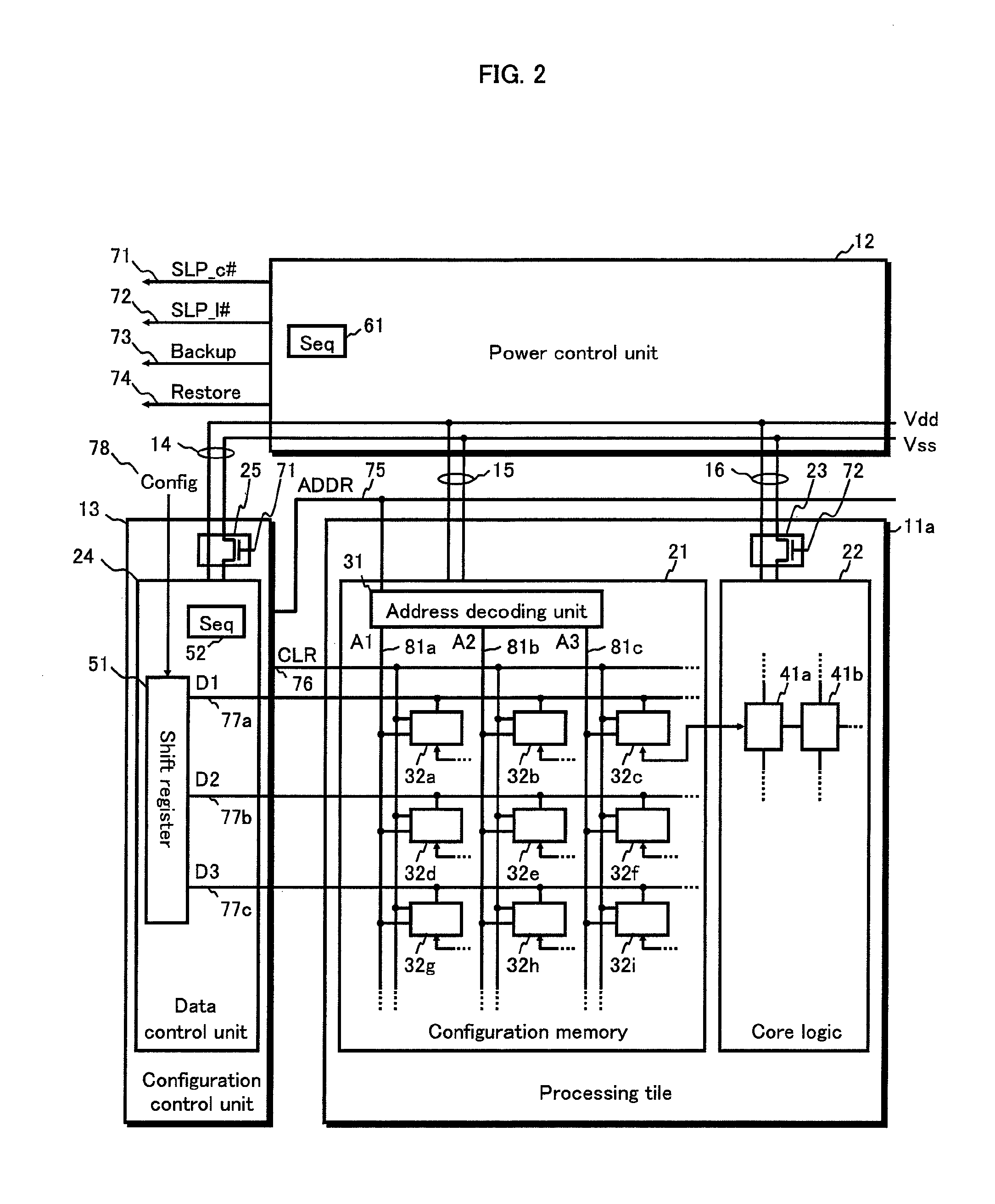
[0074]The programmable device 2 includes a plurality of processing tiles 11 (11a, 11b . . . 11i) each of which is a programmable logical processing unit, a configuration control unit 13 that delivers the configuration information to the processing tiles 11 and performs programming, a power control unit 12 that controls power output by the power supply unit 4, and power supply lines 14 to 16.

[0075]Also, each of the processing tiles 11a to 11i include a configuration memory 21 that stores the configuration information, a core logic 22 that performs calculation processing according to content stored in the configuration memory 21, and a power gating switch 23 f...

embodiment 2

2. Embodiment 2

[0166]In embodiment 1, as shown in FIG. 7B, when assigning a user circuit to a programmable device, all of the processing tiles need not necessarily be used, and depending on how the user circuits are assigned, a portion of the processing tiles may become the unused area 209.

[0167]Although supplying power to the processing tiles in the unused area 209 is not necessary, in the structure of the processing system in embodiment 1, power supply to the configuration memory cannot be cut off.

[0168]Also, although the configuration memory is configurable as a low-leak transistor, there are cases in which, when the capacity is large, the amount of leaked power as a whole cannot be ignored.

[0169]In view of this, in embodiment 2, the programmable device is configured so that the power supply to the configuration memory can also be cut off, thereby further improving energy conservation.

[0170]The following description focuses on the differences from embodiment 1.

2.1 Structure

[0171]...

embodiment 3

3. Embodiment 3

[0187]In embodiment 2, function assignment is performed on the user circuit as shown in FIG. 7(b), and the user circuit is caused to operate so that only one module at a time is in the active state, as shown in FIG. 7(c). In this case, most of the device is in an inactive state, and the use efficiency of circuit resources is low.

[0188]The programmable device pertaining to embodiment 3 is a dynamic reconfigurable device that is reconfigurable during operation.

[0189]Specifically, as shown in FIG. 12, in one device 400, processing is advanced while a module A (401), a module B (402), and a module C (403) are dynamically assigned according to a timetable.

[0190]Here, when changing the configuration from module A (401) to module B (402), even when an internal state of the processing tile belonging to module A (401) is caused to be saved in a corresponding memory cell (the memory cell that stores therein the configuration information for initializing the processing tile) as ...


PUM


Abstract

A programmable device operates at high speed while reducing power consumption. The programmable device includes a plurality of processing tiles each including a configuration memory and a core logic unit, a configuration control unit for programming them, and a power control unit for cutting off a power supply depending on an operating state. The power supply of the core logic unit is cut off after saving the internal state of the core logic unit in the configuration memory, and power is supplied again to the core logic unit before the internal state is restored from the configuration memory to the core logic unit, thus saving power while maintaining the internal state.

Description

BACKGROUND OF THE INVENTION[0001]1. Technical Field[0002]The present invention relates to power saving in a programmable device.[0003]2. Background Art[0004]In recent years, a dynamic reconfigurable device has been developed that can change a configuration in a short time such as from several microseconds to several nanoseconds, even when operating (see non-patent document 1).[0005]When the device is made to be more high-speed and miniaturized, there is a problem of leaked power, which takes up as much as approximately 50% of the total consumed energy of a chip.[0006]As a measure against this problem, a technology is disclosed in patent document 1, in which power gating technology is applied and power supply is cut off to any circuit block that is not assigned a function and is unused, or is in a wait state.[0007]Patent document 1: U.S. Pat. No. 7,098,689[0008]Non-patent document 1: Masato Motomura, “A Dynamically Reconfigurable Processor Architecture”, Microprocessor Forum, October...

Claims


Application Information

Patent Timeline
Patent Type & Authority Patents(United States)
IPC IPC(8): G06F7/38H03K19/177H01L25/00
CPCH03K19/17772H03K19/17784
Inventor NISHIOKA, SHINICHIRO
Owner PANASONIC CORP
Why Eureka
Try Eureka