Sensor for sensing airborne particles

a technology of airborne particles and sensors, which is applied in the direction of electrostatic separation, instruments, chemistry apparatuses and processes, etc., can solve the problems of limiting the general applicability of the thermal chimney effect, reducing the efficiency of the sensor, and reducing the energy consumption of the sensor. , to achieve the effect of no energy, no audible noise, and no energy

Active Publication Date: 2011-09-08
KONINKLIJKE PHILIPS ELECTRONICS NV
View PDF24 Cites 29 Cited by
  • Summary
  • Abstract
  • Description
  • Claims
  • Application Information

AI Technical Summary

Benefits of technology

[0007]It is an object of the present invention to provide an improved UFP sensor for use in environments wherein noiseless operation of the sensor is preferred. It is desirable that the components which are active in creating the airflow through the sensor should consume virtually no energy (or at least a reduced amount of energy), be durable, compact, and generate virtually no audible noise (or at least very low audible noise).
[0021]In an advantageous embodiment of the invention, the sensor further comprises an optical particle detection unit capable of optically detecting airborne particles in the airflow. Airborne particles can be easily detected only when they are larger than about 300 nm. With a suitably configured optical particle detection unit, it is even possible to distinguish several size classes of particles in the 300 nm-10 μm particle size interval. The addition of an optical particle detection unit to the sensor enables not only the sensing of ultrafine particles in the 10-300 nm size range but also the sensing of fine particles larger than 300 nm. This is beneficial because any presence of airborne particles smaller than 10 μm can be hazardous in view of their ability to be inhaled and deposit deep in the respiratory tract. Airborne particles larger than 300 nm cannot easily be detected via a measurement of their charge because the contribution of the particle charge associated with particles larger than 300 nm to the total particle charge sensed by the particle sensing section is usually negligible when compared with the particle charge associated with airborne particles smaller than 300 nm. At the same time, airborne particles larger than 300 nm are easier detected by optical means than particles smaller than 300 nm. Hence, the information obtained with the optical particle detection unit, which may be provided to an evaluation unit as a measurement signal, complements the information obtained with the charged-particle sensing section. The optical particle detection unit is preferably arranged upstream from the discharge electrode to avoid any charged-particle precipitation inside the optical particle detection unit.
[0031]In a further advantageous embodiment of the invention, one or both ends of the passage is shielded from direct exposure to the environment by a shielding plate facing the aperture. This measure prevents that the ionic wind-induced airflow through the passage inside the sensor becomes readily affected by air movements induced by spatial air pressure gradients in the environment wherein the sensor is present. This enhances the reliability of the sensor measurements and prevents interference by environmental conditions.

Problems solved by technology

Because inhalation of UFPs is known to be harmful to human health, UFP sensors may be used for monitoring the quality of air, in particular the UFP pollution level in the air, both in the indoor and outdoor environment.
Even though FPs as a class of particles are believed to be less hazardous than UFPs, any airborne particle smaller than 10 μm can potentially create hazard because it is inhalable and capable of reaching and depositing in the deep alveolar region of the lungs.
To interfere as little as possible with normal human activities, UFP sensors should be small, unobtrusive, and also noiseless.
The thermal energy needed for inducing such an airflow makes operation of the sensor less economical.
Moreover, the thermal chimney effect is only effective when the air passage inside the sensor is positioned vertically, thus limiting the general applicability of the thermal chimney effect.

Method used


Image

  • Sensor for sensing airborne particles
  • Sensor for sensing airborne particles
  • Sensor for sensing airborne particles

Examples


Embodiment Construction

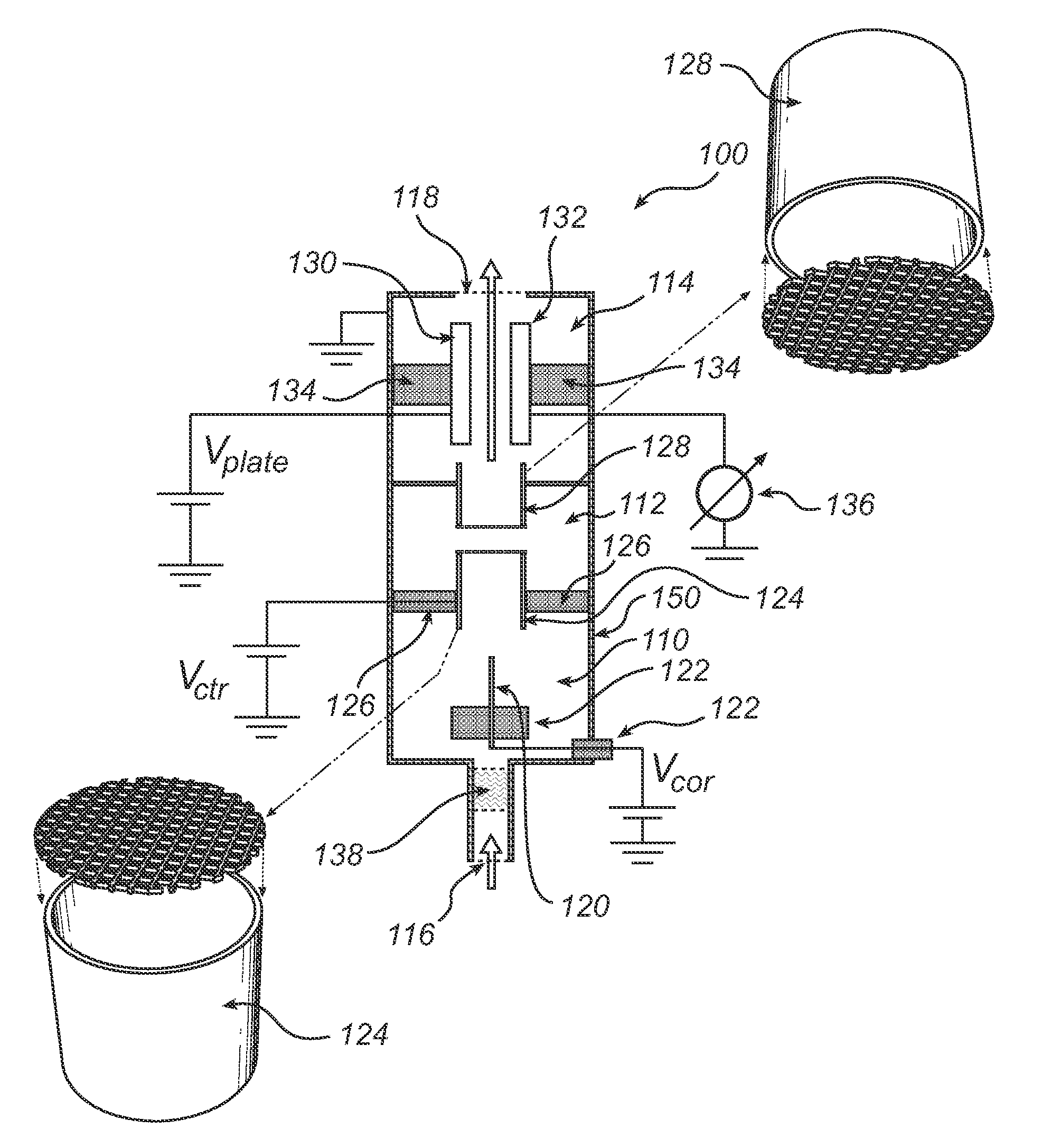
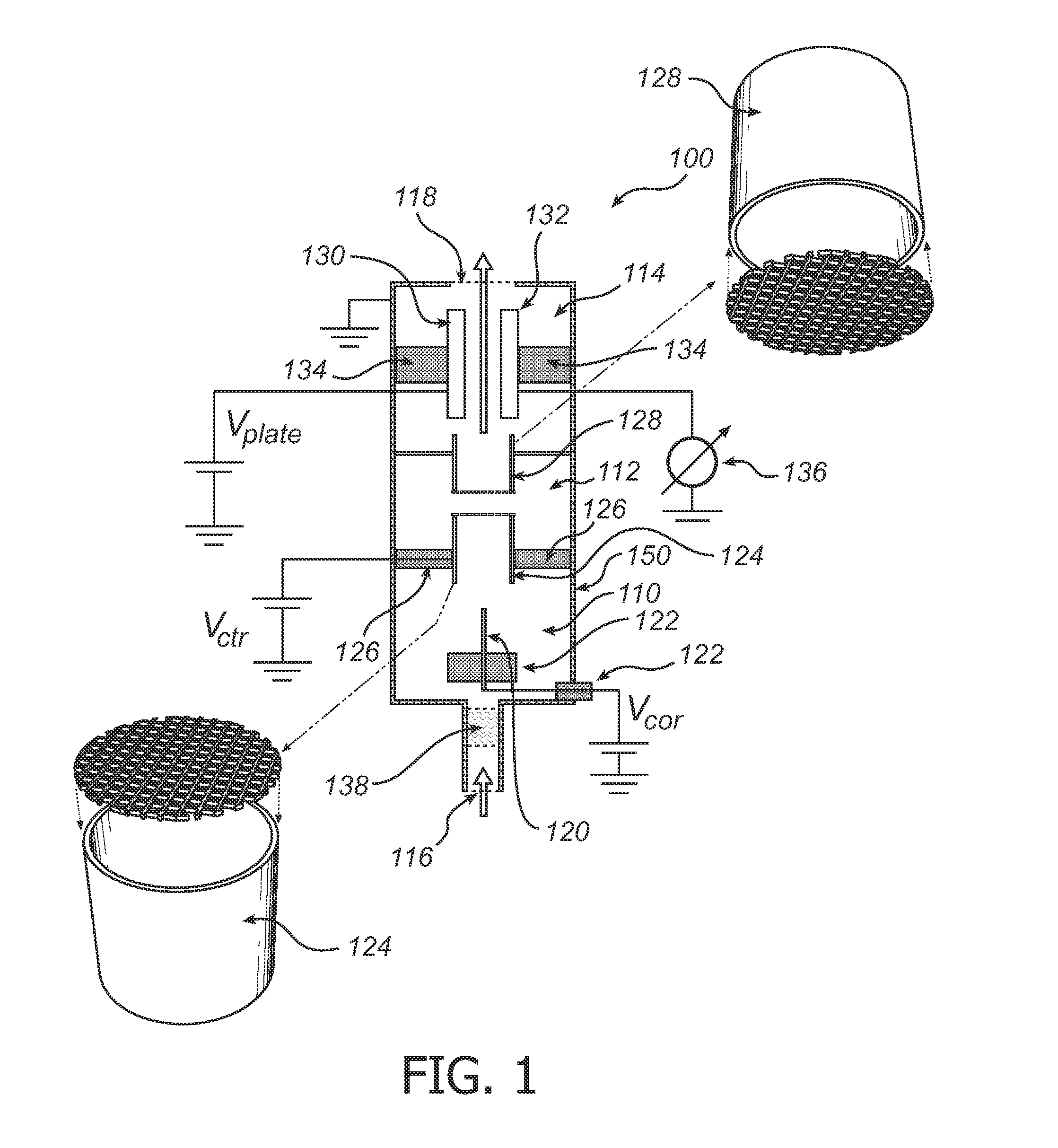
[0051]FIG. 1 shows a UFP sensor 100 according to a particular embodiment of the present invention. The sensor 100 comprises an air-filled central passage comprising three connected sections 110, 112, 114, wherein the first section 110 for charging particles extends in the direction of the passage from an inlet section 116 to a counter electrode 124; the second section 112 extends from the counter electrode 124 to a screening electrode 128; and the third section 114, intended for the sensing of charged particles, extends from the screening electrode 128 to an outlet section 118. The inlet section 116 and outlet section 118 are provided in the form of apertures in a housing 150 of the sensor 100 that is connected to earth or some reference (zero) potential.

[0052]In the first section 110, there is provided a high-voltage corona discharge electrode 120, which is connected to a potential Vcor and electrically insulated from other portions of the sensor 100 by means of insulator 122. The ...


PUM

PropertyMeasurementUnit
angleaaaaaaaaaa
diameteraaaaaaaaaa
number-averaged particle sizeaaaaaaaaaa

Abstract

A particle sensor is disclosed capable of sensing airborne particles larger than about 10 nm in an airflow passing through a passage inside the sensor. The sensor comprises a high-voltage discharge electrode for generating airborne unipolar ions that charge the airborne particles in the airflow. The generated ions are furthermore used to set-up an ionic wind between the discharge electrode and a counter electrode inside the sensor. The ionic wind is the driving force for maintaining the airflow through the sensor and allows sensor operation to occur free of audible noise. The presence of charged particles in the airflow is measured by an electrical current meter in the particle sensing section which measures the particle-bound charge that precipitates per unit time on the surface of a precipitation electrode after all airborne ions have been removed from air by a separate screening electrode positioned upstream of the particle sensing section.

Description

FIELD OF THE INVENTION[0001]The present invention relates to a sensor for sensing airborne particles larger than 10 nm. The invention also relates to an air handling system comprising the sensor, and to a method for sensing airborne particles larger than 10 nm.BACKGROUND OF THE INVENTION[0002]Airborne ultrafine particles (UFPs) are particles with a diameter in the range approximately from 10 to 500 nm. In the technical literature, the term UFP is sometimes also used for particles with a diameter below 300 nm. Because inhalation of UFPs is known to be harmful to human health, UFP sensors may be used for monitoring the quality of air, in particular the UFP pollution level in the air, both in the indoor and outdoor environment. Appropriate measures to reduce exposure to airborne UFPs can then be taken when deemed necessary on the basis of the UFP sensor signals. For instance, an air processing system arranged to remove airborne UFPs from the indoor environment can be run more economica...

Claims


Application Information

Patent Timeline
Patent Type & Authority Applications(United States)
IPC IPC(8): G01N15/02
CPCG01N1/2202G01N15/0266G01N15/0205B03C3/017B03C3/08B03C3/12B03C3/38B03C3/41B03C3/47G01N1/2205
Inventor MARRA, JOHANNES
Owner KONINKLIJKE PHILIPS ELECTRONICS NV
Why Eureka
Try Eureka