Device for reducing flow noise and valve

a flow noise and valve technology, applied in the direction of mechanical equipment, pipe elements, transportation and packaging, etc., can solve the problems of significant flow velocity in the generation of noise and the increase of the noise level produced by the free jet, and achieve the effect of reducing flow noise in flow control

Active Publication Date: 2017-06-13
NELES FINLAND OY
View PDF21 Cites 14 Cited by
  • Summary
  • Abstract
  • Description
  • Claims
  • Application Information

AI Technical Summary

Benefits of technology

[0006]An object of this invention is to solve the above-described problem and provide a solution which enables flow noise to be reduced efficiently in flow control. This object is achieved by a device as claimed in independent claim 1, and a valve as claimed in independent claim 13.
[0007]In order to reduce flow noise, a device is utilized wherein a fluid flow is led to a chamber via an inlet aperture or inlet apertures, the chamber having a larger cross-sectional area than that of the inlet apertures of said chamber in total, and the flow is forwarded from the chamber via a plurality of small outlet apertures, each outlet aperture having a smaller flow cross-sectional area than that of the chamber and a larger combined cross-sectional area than that of the inlet apertures of said chamber in total. This enables the chamber to be used for achieving a controlled change in the flow and the flow to be divided into smaller portions in an as efficient and noise-reducing manner as possible. The device may be utilized alone in a pipeline, or it may be integrated in a valve.

Problems solved by technology

It is not in all situations purposeful to increase the wall thicknesses of pipelines and the devices included therein e.g. by noise reducing materials.
A noise level produced by a free jet increases strongly as flow velocity increases.
In connection with a control valve in a pipeline flow, a situation similar to that of a free jet occurs at the last choke point leading to the pipeline, in which case the flow velocity therein is significant in the generation of noise.

Method used


Image

  • Device for reducing flow noise and valve
  • Device for reducing flow noise and valve
  • Device for reducing flow noise and valve

Examples


first embodiment

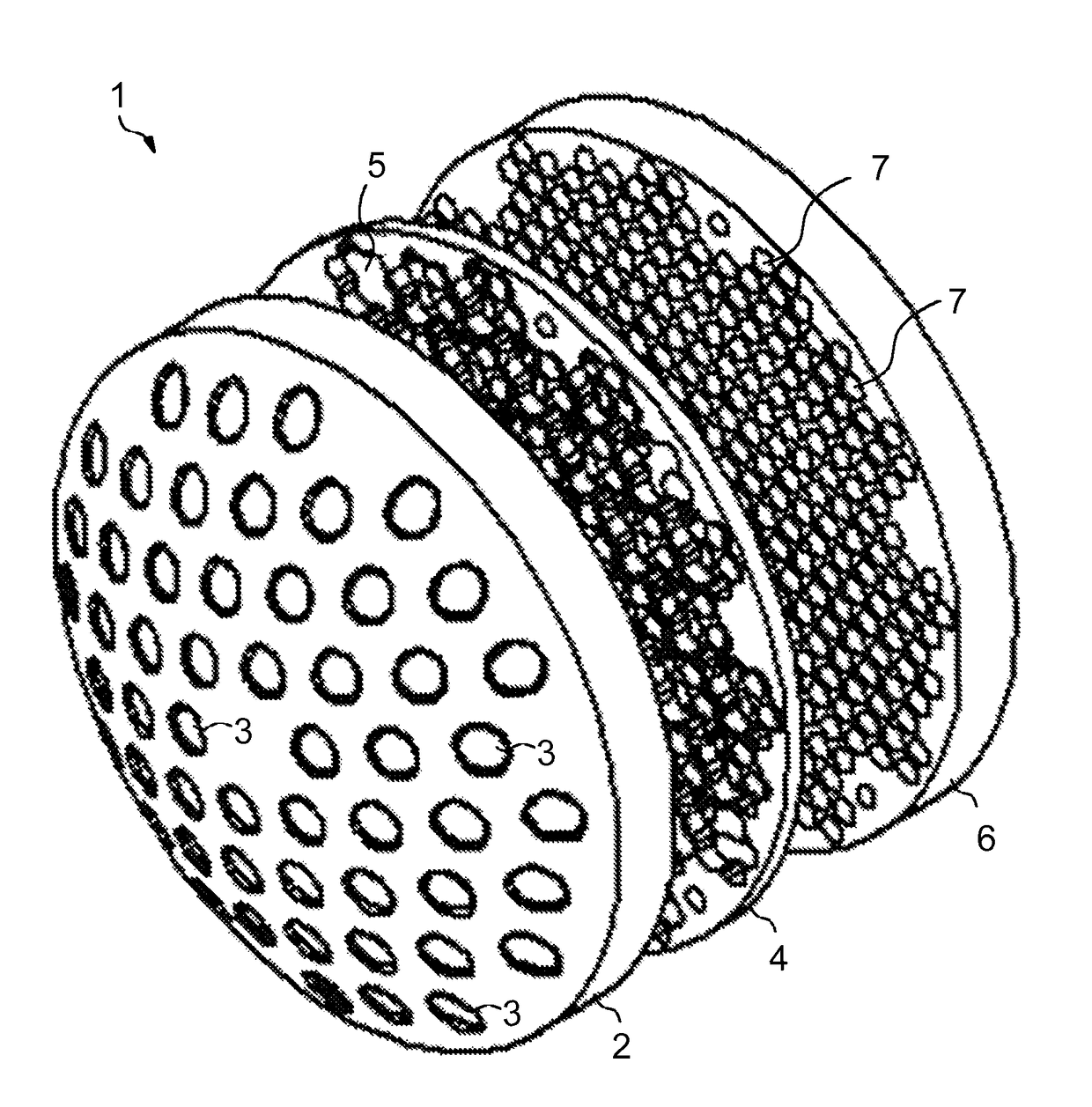
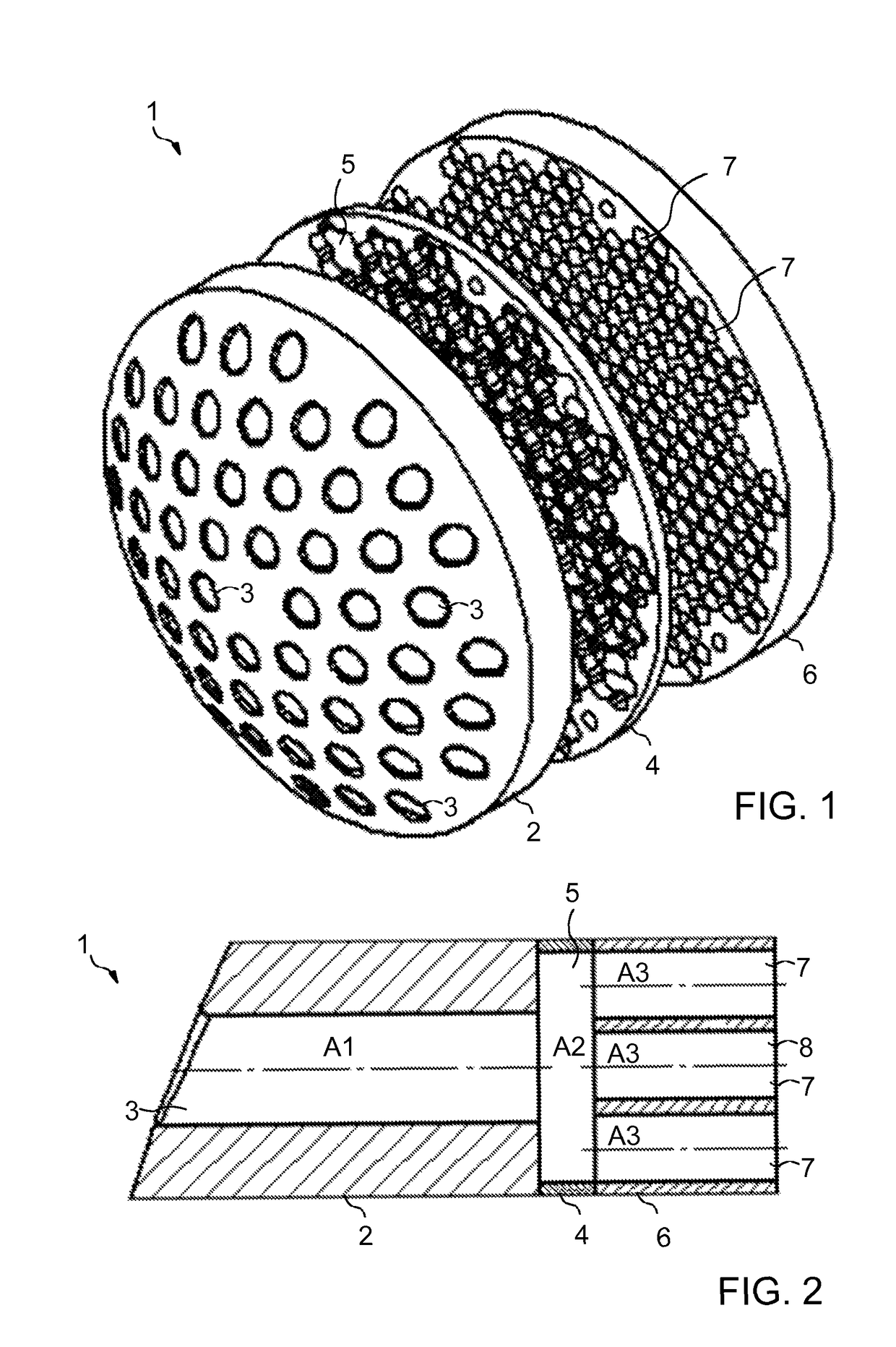
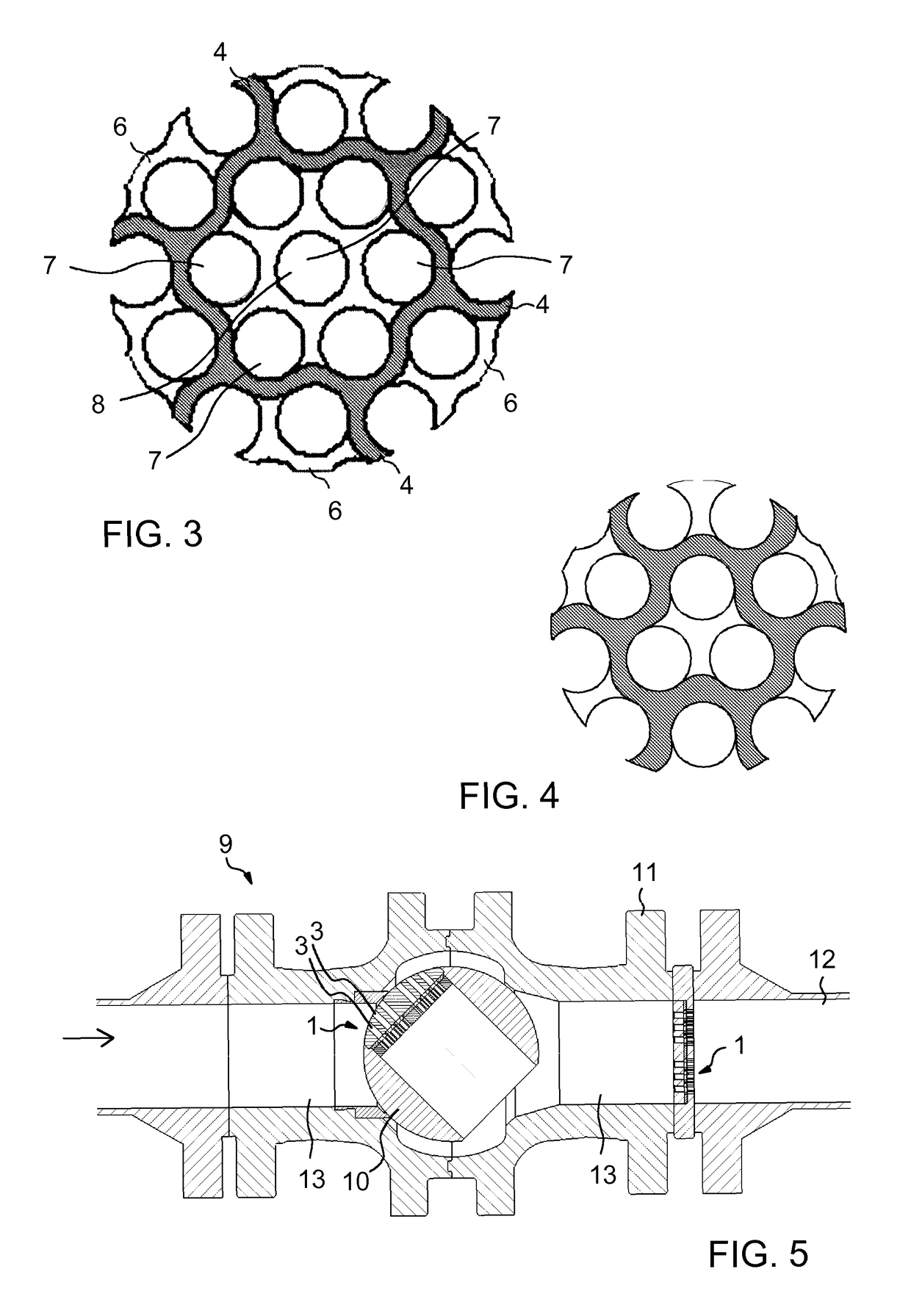
[0018]FIGS. 1 to 3 illustrate a device. FIG. 1 is an exploded view of the device 1, FIG. 2 is a partial section of the device 1 of the figure, and FIG. 3 shows the design of the transverse flow area of chambers.

[0019]In the following, it is by way of example assumed that the device is implemented by means of three parts (e.g. three plates) to be placed against one another, as shown by way of example in the figures. However, it is to be noted that this is not necessary in all embodiments since the necessary apertures and chambers may also be implemented in other ways, e.g. by machining both inlet and outlet apertures as well as chambers in some of the shown parts.

[0020]In the exemplary case of FIG. 1, a part 2 situated on the left has an inlet surface which is provided with a plurality of inlet apertures 3 for receiving a fluid flow. A middle part 4 is provided with chambers 5, in which case the inlet apertures 3 are chamber-specific, i.e. each inlet aperture opens up into one chambe...

second embodiment

[0040]FIG. 8 illustrates the device. The embodiment of FIG. 8 largely corresponds to the embodiment of FIG. 1, wherefore the embodiment of FIG. 8 will be explained in the following primarily by disclosing differences from the embodiment of FIG. 1.

[0041]The left half (the inlet aperture 3, the chamber 5 and the outlet apertures 7) of the device 1′ of FIG. 8 matches completely the device 1 shown in FIG. 1. In this embodiment, however, more than one corresponding device is arranged successively. Thus, the outlet apertures 7 simultaneously form inlet apertures for a second chamber 5′ such that each outlet aperture 7 leads to a second individual chamber 5′ of its own. As distinct from FIG. 8, it is also feasible that more than one outlet aperture 7 leads to each of the second chambers 5′. Each of the second chambers 5′, in turn, is provided with individual outlet apertures 7′ of its own, wherefrom the flow is allowed to advance from said second chamber 5′. The cross-sectional area of eac...

third embodiment

[0042]FIG. 9 illustrates the device. The embodiment of FIG. 9 largely corresponds to the embodiment of FIG. 1, wherefore in the following the embodiment of FIG. 9 will be explained primarily by disclosing differences from the embodiment of FIG. 1.

[0043]The left half (the inlet aperture 3, the chamber 5 and the outlet apertures 7) of the device 1″ of FIG. 9 matches completely the device 1 shown in FIG. 1. However, in this embodiment, the outlet apertures 7 simultaneously form inlet apertures for a second chamber 5″. Only one single second chamber 5″ is in use which receives the flow from all outlet apertures 7 of the chamber 5. From the second chamber 5″ the flow is allowed to advance via a plurality of outlet apertures 7.


PUM


Abstract

Disclosed is a device for reducing flow noise. In order to achieve a low flow noise, the device includes inlet apertures for receiving a fluid flow, chambers into which one or more inlet apertures open up, a cross-sectional area of a single chamber being larger than a combined flow cross-sectional area of the inlet apertures opening up thereto, and chamber-specific outlet apertures for forwarding the fluid flow from the chamber, a flow cross-sectional area of each outlet aperture being smaller than the cross-sectional area of the chamber, and the combined flow cross-sectional area of all outlet apertures of the single chamber being larger than the combined flow cross-sectional area of the inlet apertures opening up into said chamber.

Description

FIELD OF THE INVENTION[0001]This invention relates to reducing flow noise and to a valve, and particularly to a device enabling pipeline flow control to be implemented in a noise reducing manner.DESCRIPTION OF PRIOR ART[0002]In connection with flow control, it is important to manage noise such that it is not harmful to the environment or those working in the vicinity. It is not in all situations purposeful to increase the wall thicknesses of pipelines and the devices included therein e.g. by noise reducing materials. Therefore, it is also necessary to influence the flow itself in a manner in which the noise caused by the flow may be reduced.[0003]A noise level produced by a free jet increases strongly as flow velocity increases. In connection with a control valve in a pipeline flow, a situation similar to that of a free jet occurs at the last choke point leading to the pipeline, in which case the flow velocity therein is significant in the generation of noise. A low flow velocity ma...

Claims


Application Information

Patent Timeline
Patent Type & Authority Patents(United States)
IPC IPC(8): F16K47/02F16K47/04F16K47/08F16L55/033F16L55/027F16L55/04
CPCF16K47/02F16K47/04F16K47/045F16K47/08F16L55/02718F16L55/02781F16L55/033F16L55/04Y10T137/86718Y10T137/86743Y10T137/86751Y10T137/86863F16L55/00
Inventor YLI-KOSKI, ESKOWESTEN, TOMI
Owner NELES FINLAND OY
Why Eureka
Try Eureka