
Fuel efficiency of road vehicles

a technology for road vehicles and fuel efficiency, applied in the field of road vehicles, can solve the problems of complex and costly incorporation of recesses, and achieve the effects of improving the aerodynamic efficiency of road vehicles, increasing aerodynamic efficiency, and promoting laminar flow

Active Publication Date: 2017-06-20
BACON ANDREW
View PDF32 Cites 13 Cited by
  • Summary
  • Abstract
  • Description
  • Claims
  • Application Information

AI Technical Summary

Benefits of technology

The patent text describes an aerodynamic unit for vehicles that improves its efficiency by reducing turbulence and drag effects. This is achieved by guiding the air flow over the vehicle's roof in a generally downwards direction, using a guide portion attached to the roof. The patent also describe an attachment system for the aerodynamic unit to various road vehicles, such as cab and trailer. The attachment system includes two side fins that are attached to the roof of the vehicle, and an air flow guide that extends between the fins. This guide helps to position the aerodynamic unit correctly on the vehicle roof. Overall, this invention enhances the aerodynamic performance of road vehicles, leading to improved fuel efficiency.

Problems solved by technology

However, the incorporation of such a recess can be complex and costly.

Method used


Image

  • Fuel efficiency of road vehicles
  • Fuel efficiency of road vehicles
  • Fuel efficiency of road vehicles

Examples


Embodiment Construction

)

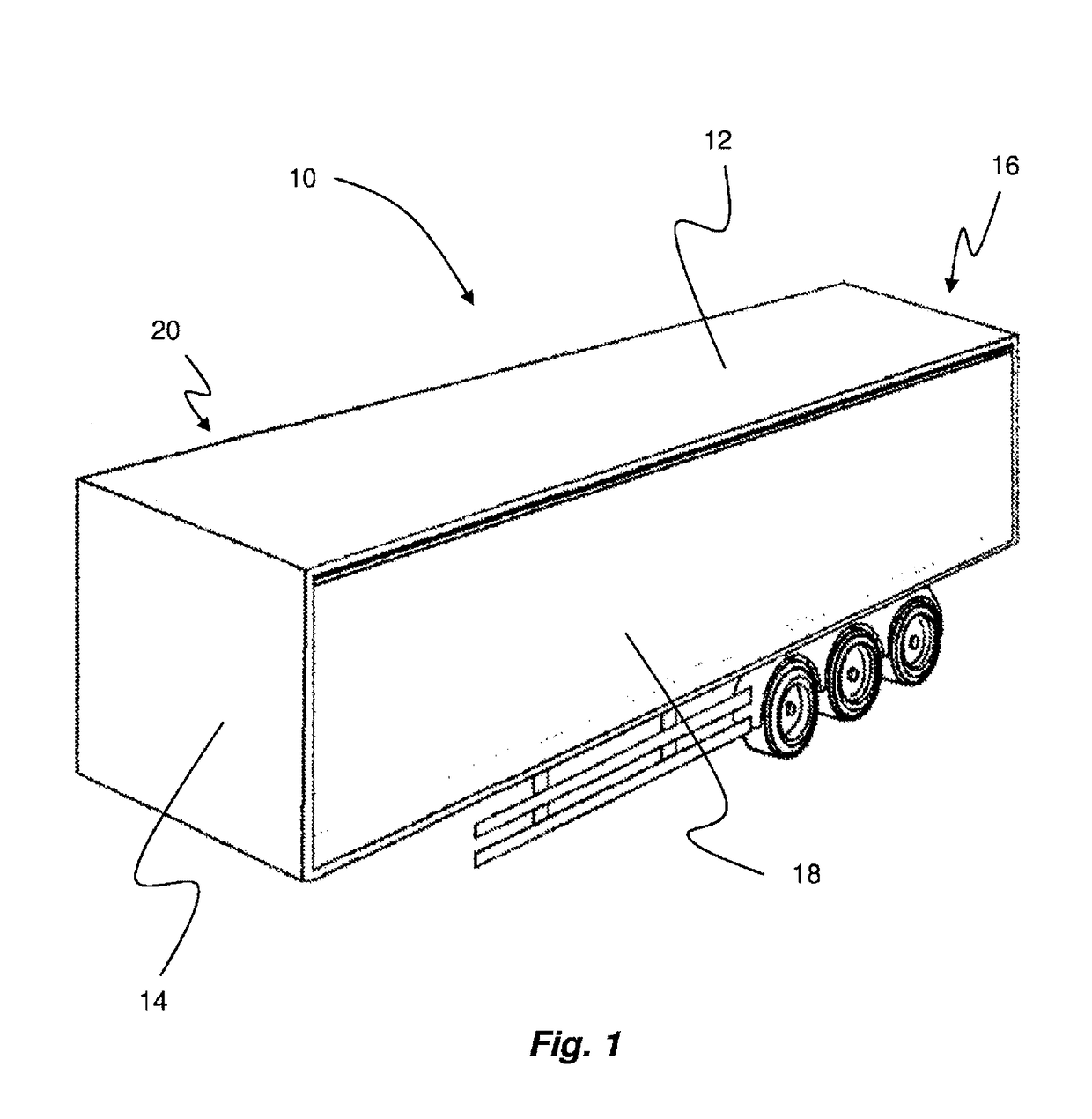
[0059]Referring to FIG. 1, a conventional trailer is indicated generally at 10. The trailer 10 is of a box type and includes a roof 12, a front wall 14, a rear wall 16, and two side walls 18 and 20. As will now be described, the invention provides an aerodynamic unit that can be attached to a conventional trailer (e.g. a trailer with substantially square corners), or alternatively an unconventional trailer (e.g. with radius corners) where appropriate, to improve the aerodynamic properties of the trailer.

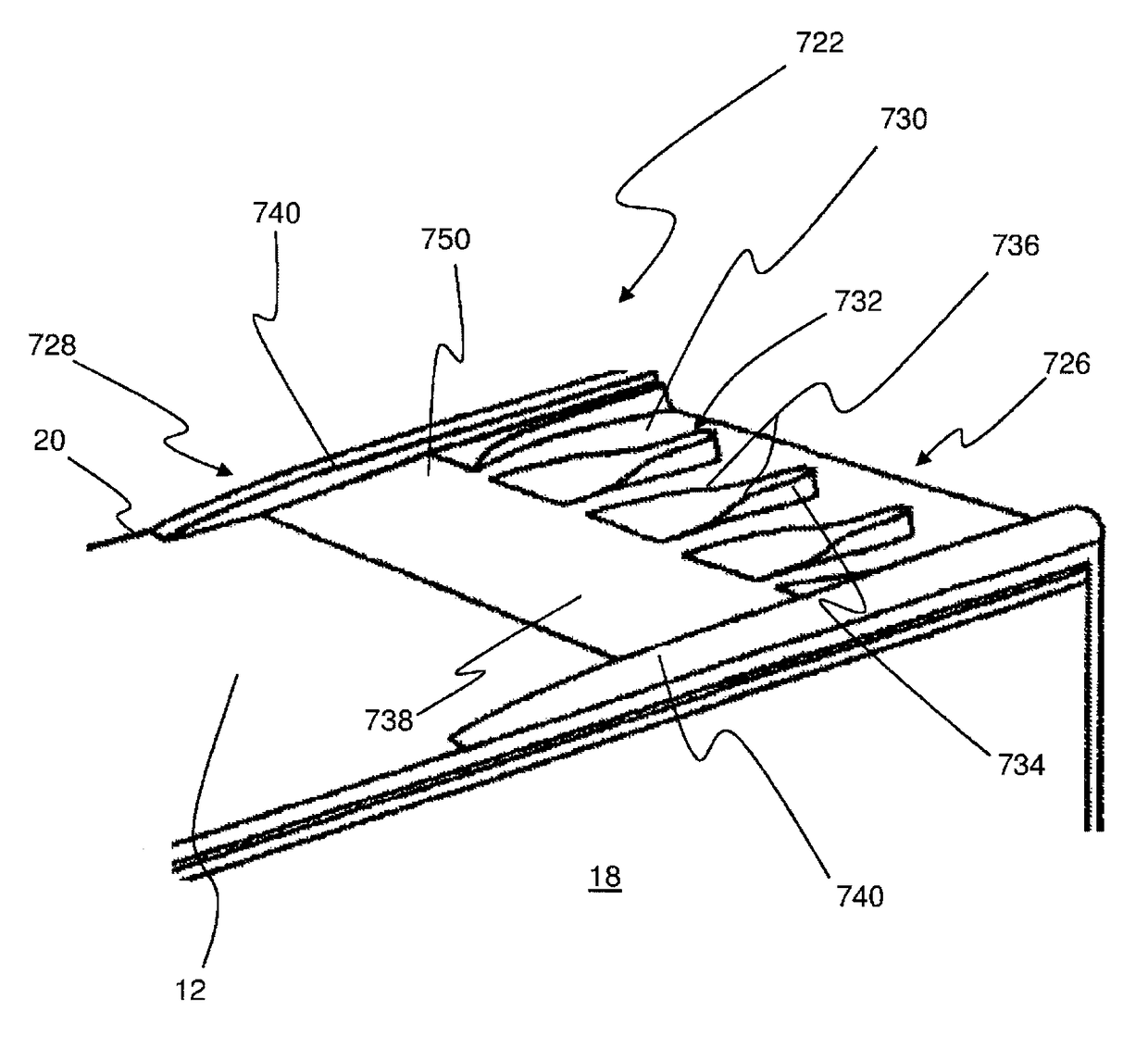
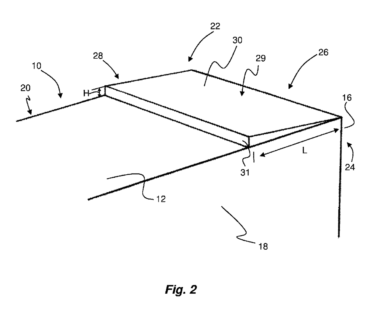
[0060]FIG. 2 shows a rear portion of the trailer unit 10, modified for improved aerodynamic properties and therefore improved fuel economy. An aerodynamic unit 22 is positioned on the roof 12 proximal to the rear 24 of the trailer unit 10, i.e. near the rear wall 16, and in this embodiment is adjacent the rear wall 16. In alternative embodiments, the aerodynamic unit 22 may be spaced inwardly from the rear end of the trailer 10. However, it is preferable from an aerodynamic efficien...


PUM


Abstract

An aerodynamic unit is attached onto a roof of a road vehicle so that air passes over the unit during forward movement of the road vehicle. The unit has a first end for positioning distal to a rear end of a vehicle roof and a second end for positioning proximal a rear end of a vehicle roof. The unit includes an inclined guide portion which decreases in height in a direction towards the trailing end of the unit. The unit also includes a flow director, which directs air flow to the guide portion, disposed at or near the leading end of the aerodynamic unit. The flow director has a height increasing in a direction from the leading end towards the trailing end. The unit may include vortex generators protruding from the guide portion. A fin may extend along each side of the unit in a direction between the trailing end and the leading end.

Description

FIELD OF THE INVENTION[0001]The present invention relates to road vehicles, more particularly, but not exclusively, to road haulage vehicles, buses and cars of the “people carrier” type.BACKGROUND OF THE INVENTION[0002]It is known that improvements in vehicle performance and fuel consumption can be achieved through improvements in the aerodynamic structure of a vehicle. Such improvements are sought in the design of vehicles in the haulage industry, for example articulated vehicles of the kind having a cab and trailer.[0003]One method of improving the aerodynamic structure of a trailer of a haulage vehicle is to modify the roof of the trailer so that it defines a recess having a surface inclined downwardly below the level of the roof at the rear of the trailer, see for example the trailer shown in GB2271323. However, the incorporation of such a recess can be complex and costly.SUMMARY OF THE INVENTION[0004]An aim of the present invention is to alleviate one or more problems associate...

Claims


Application Information

Patent Timeline
Patent Type & Authority Patents(United States)
IPC IPC(8): B62D35/00
CPCB62D35/001
Inventor BACON, ANDREW
Owner BACON ANDREW
Learn More