Pressing spray mop

a spray mop and pressing technology, applied in the field of mop, can solve the problems of inconvenient maintenance, failure of spraying mop, and malfunction of connecting lines, and achieve the effect of preventing further loosening among structures

Active Publication Date: 2017-06-27
JIAXING JACKSON TRAVEL PROD CO LTD
View PDF8 Cites 5 Cited by
  • Summary
  • Abstract
  • Description
  • Claims
  • Application Information

AI Technical Summary

Benefits of technology

[0005]The primary object of the present invention is to solve issues of a conventional mop spray having increased labor hours and poor assembly caused by the assembly involving external components.
[0016]With the above technical solution, the present invention provides following features compared to the prior art. In the present invention, the assembly of the water tank seat and the mop rod can be accomplished without involving external components. Further, the stability of the assembled water tank seat and mop rod is substantial to the stability of an assembly completed with the use of external components. Further, as the assembly of structures of the present invention does not involve external components, the issue of loosening among the structures can further be prevented while the user operates the pressing spray mop. In addition, with the angle between the mop rod and the mop head, the mobile connecting mechanism may enter the utilization state or the locked state, so as to prevent an unintentional user touch from pressing the spray mop for spraying.

Problems solved by technology

However, due to factors such as long-term use or unsatisfactory assembly, the connecting line may become malfunctioning such that the spray mop fails to perform spraying.
Further, also because of the connecting line disposed, maintenance is made more inconvenient.
In addition, to ensure that the connecting line is reliably triggered by the lever, the mop rod of the spray mop implemented by the above technical solution cannot be adjusted in length according to actual requirements, hence disfavoring its application.
Thus, an installation process for involving these external components is increased to lead to an increase in labor hours.
Further, during the assembly process involving the external components, an issue of poor assembly may occur, such that the components may become loose and connecting points of the components may even be damaged in more severe cases, hence disfavoring mass production or user applications.

Method used


Image

  • Pressing spray mop
  • Pressing spray mop
  • Pressing spray mop

Examples


Embodiment Construction

[0024]Details and technical contents of the present invention are given with the accompanying drawings below.

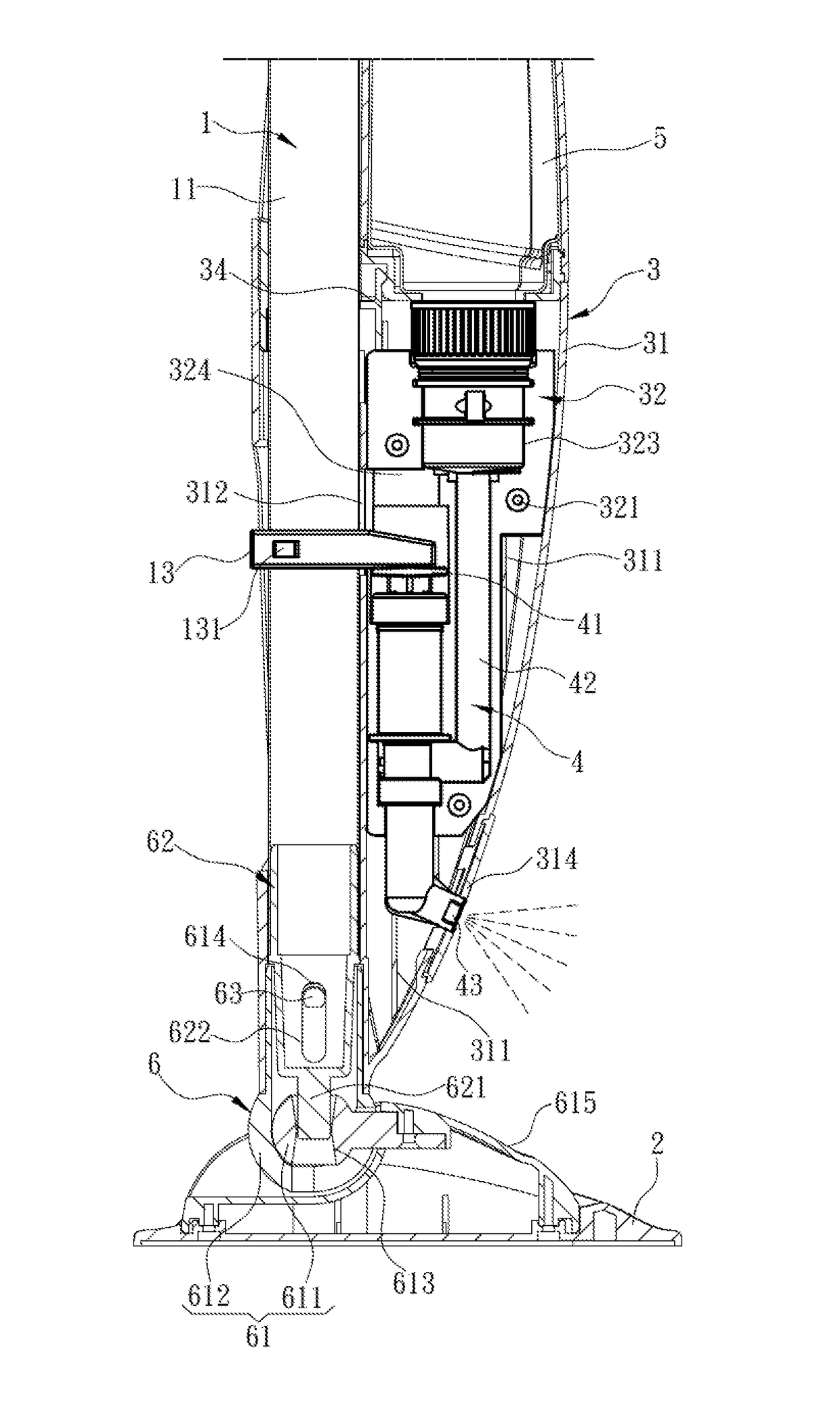
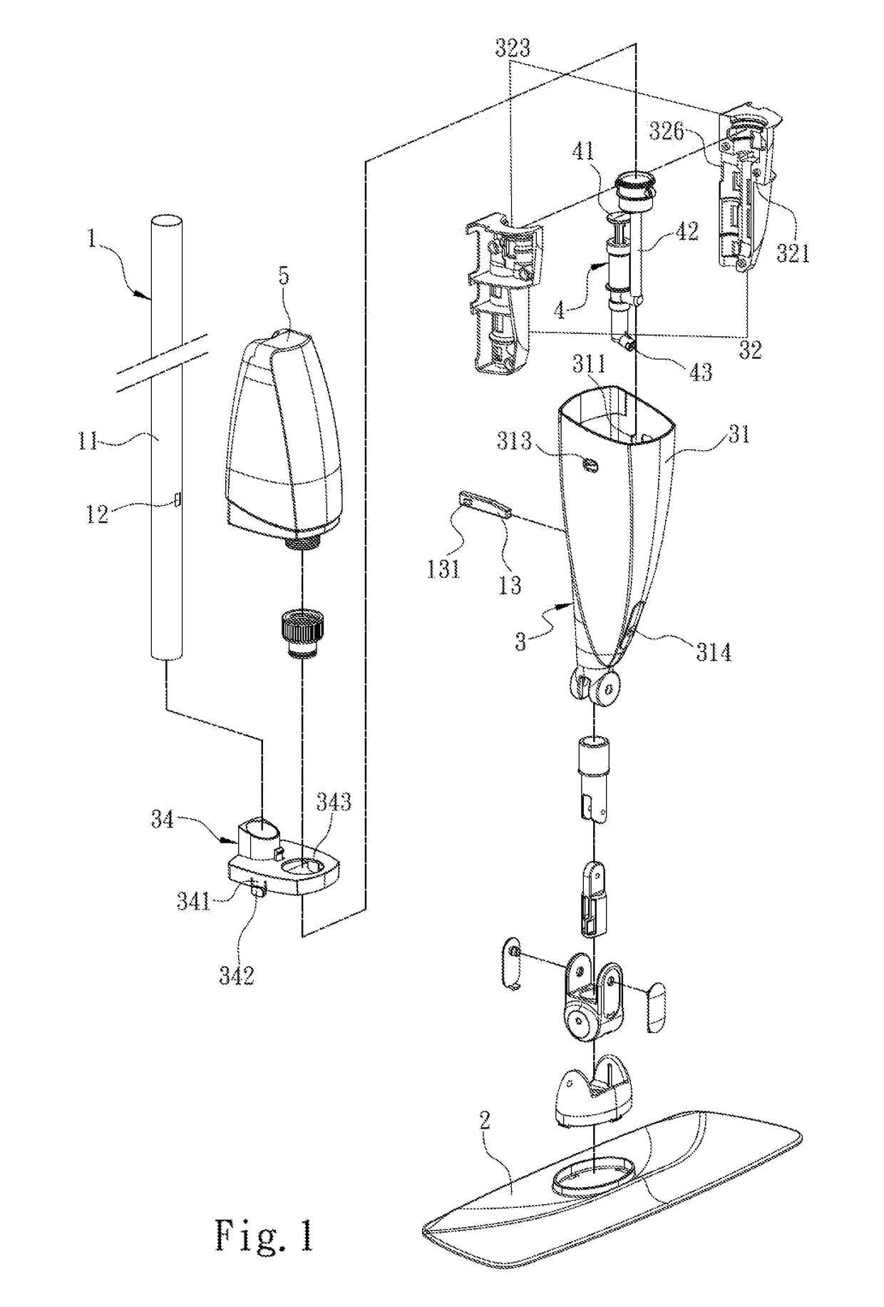
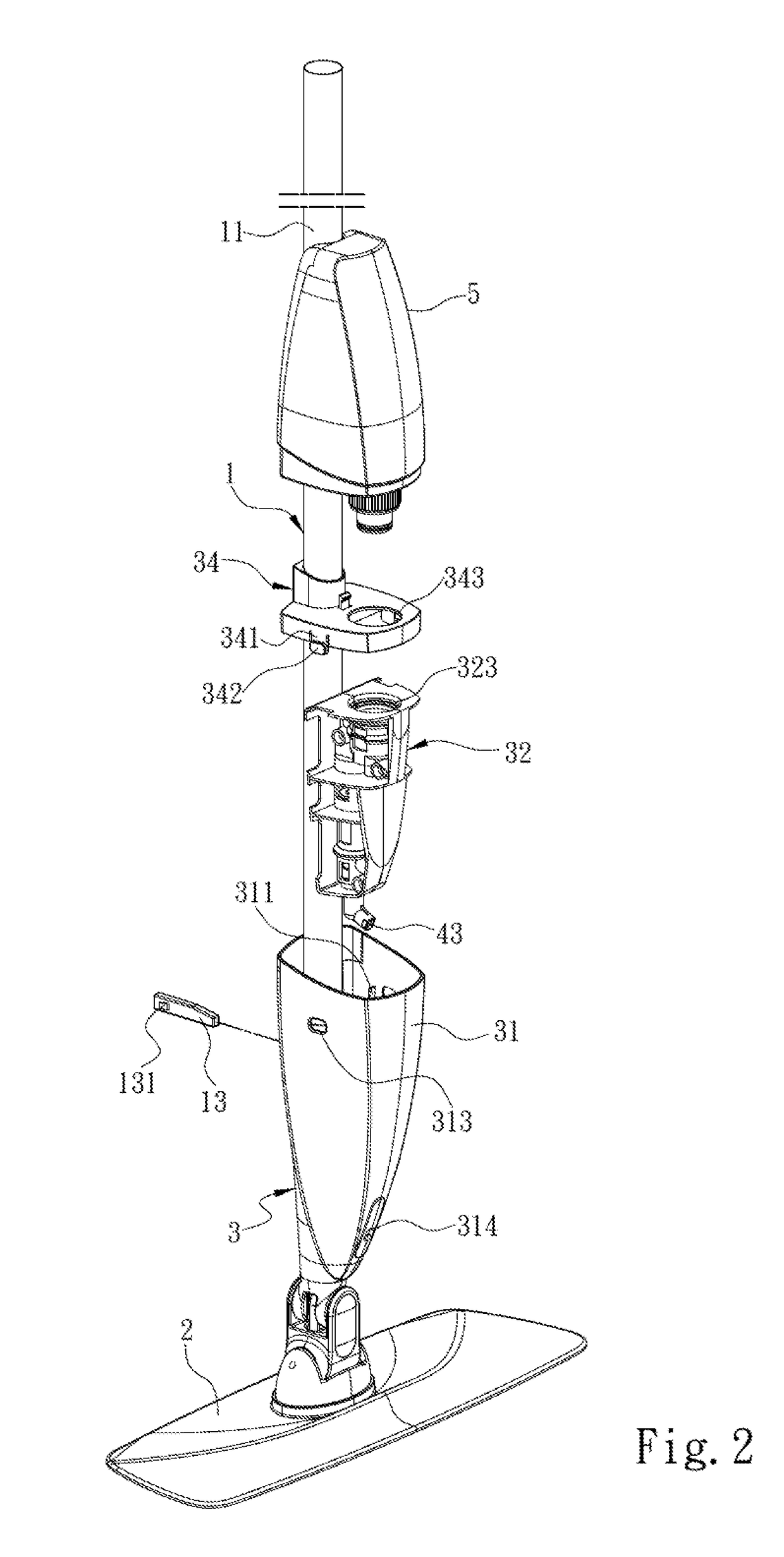
[0025]Referring to FIG. 1 to FIG. 3, the present invention provides a pressing spray mop. The pressing spray mop includes a mop rod 1, a mop head 2 disposed at one end of the mop rod 1, a water tank seat 3 disposed on the mop rod 1, a spray mechanism 4 installed at the water tank seat 3, and a water tank 5 installed on the water tank seat 3 and storing a cleaning liquid. The spray mechanism 4 includes a water drawing member 41, a connecting tube assembly 42 connected to the water drawing member 41 and the water tank 5, and a spray member 43 connected to the water drawing member 41. The water tank seat 3 includes a hollow housing 31 and two support half casings 32. The hollow housing 31 includes a plurality of installation ribs 311 each abutting against at least one of the support half casings 32. The installation ribs 311 are arranged at an interval in the hollow housing 31. ...


PUM


Abstract

A pressing spray mop includes a mop rod, a mop head, a water tank seat, a spray mechanism installed at the water tank seat, and a water tank installed on the water tank seat. The water tank seat includes a hollow housing, and two support half casings encapsulating the spray mechanism after having been joggled and placed in the hollow housing, and forming a movement space corresponding to a water drawing member of the spray mechanism. The hollow housing includes a through connecting hole disposed correspondingly to the movement space. The mop rod includes a rod body, a penetration opening disposed on the rod body, and a pressing pin extended into the movement space via the through connecting hole. The pressing pin is driven and displaced by the mop rod in the movement space and presses the water drawing member to cause the spray mechanism to perform spraying.

Description

FIELD OF THE INVENTION[0001]The present invention relates to a mop, and particularly to a pressing spray mop.BACKGROUND OF THE INVENTION[0002]In current common or commercially available spray mops, water spray is primarily triggered by a lever, as disclosed in the U.S. Pat. Nos. 7,048,804, 9,173,540, 8,844,088 and 6,579,023. In the above technical solutions of triggering water spray by a lever, the lever primarily serving as a trigger source is disposed on a handle of the spray mop. Thus, manufacturers need to dispose a connecting line along a mop rod of the spray mop, and a pump structure on the spray mop is then activated by the connecting line to perform water spray. However, due to factors such as long-term use or unsatisfactory assembly, the connecting line may become malfunctioning such that the spray mop fails to perform spraying. Further, also because of the connecting line disposed, maintenance is made more inconvenient. In addition, to ensure that the connecting line is re...

Claims


Application Information

Patent Timeline
Patent Type & Authority Patents(United States)
IPC IPC(8): A47L13/22A47L13/42
CPCA47L13/22A47L13/42
Inventor ZHU, XUE LINLI, JING
Owner JIAXING JACKSON TRAVEL PROD CO LTD
Why Eureka
Try Eureka