Eureka AIR delivers breakthrough ideas for toughest innovation challenges, trusted by R&D personnel around the world.

Device for measuring the variation of a capacitance and associated measuring method

a capacitance and measurement method technology, applied in the direction of resistance/reactance/impedence, pulse technique, instruments, etc., can solve the problems of degrading the sensitivity of the sensor, not desirable, etc., and achieve the effect of reducing the charging and discharging cycle time t1, reducing the electrical consumption of the capacitive sensor without degrading its sensitivity, and improving the insensitivity of the capacitive sensor

Active Publication Date: 2017-06-27
VITESCO TECH GERMANY GMBH
View PDF17 Cites 1 Cited by
  • Summary
  • Abstract
  • Description
  • Claims
  • Application Information

AI Technical Summary

Benefits of technology

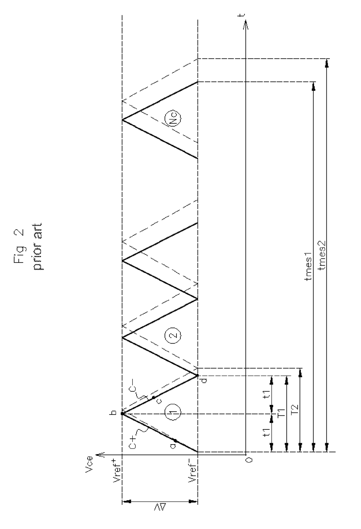
[0066]The purpose of the invention is to reduce the charging and discharging cycle time T1 of the capacitance Ce in order to lower the electrical consumption of the capacitive sensor without degrading its sensitivity. The invention also makes it possible, in a variant of the measuring device, to improve the insensitivity of the capacitive sensor with respect to external electromagnetic interference.
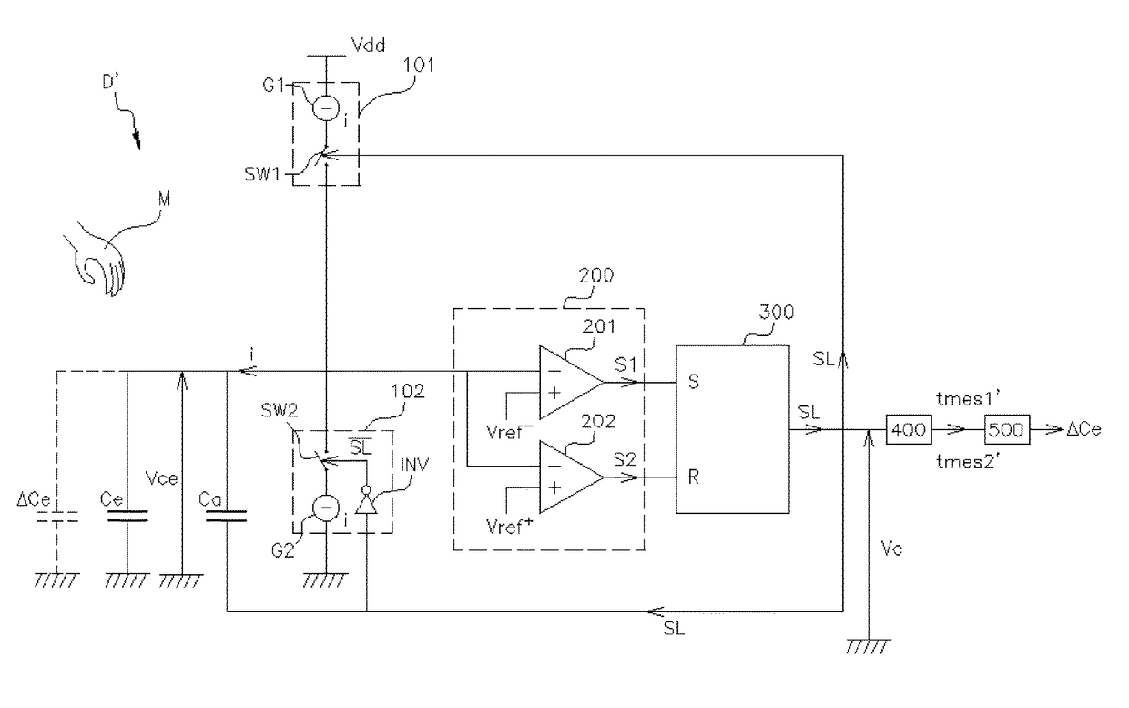
[0079]According to the invention, the presence of the additional capacitance and the particular way in which it is connected to the components of the measuring device generate a sudden increase of voltage across the terminals of the capacitance at the beginning of its charging and a sudden decrease of the voltage across the terminals of the capacitance at the beginning of its discharging. These sudden increases and decreases of voltage make it possible to reduce the charging and discharging cycle time of the said capacitance and therefore to reduce the consumption of the capacitive sensor.

Problems solved by technology

Consequently, these traditional approaches of reducing the cycle time T1 have the effect of degrading the sensitivity of the sensor, which is not desirable.

Method used


Image

  • Device for measuring the variation of a capacitance and associated measuring method
  • Device for measuring the variation of a capacitance and associated measuring method
  • Device for measuring the variation of a capacitance and associated measuring method

Examples


Embodiment Construction

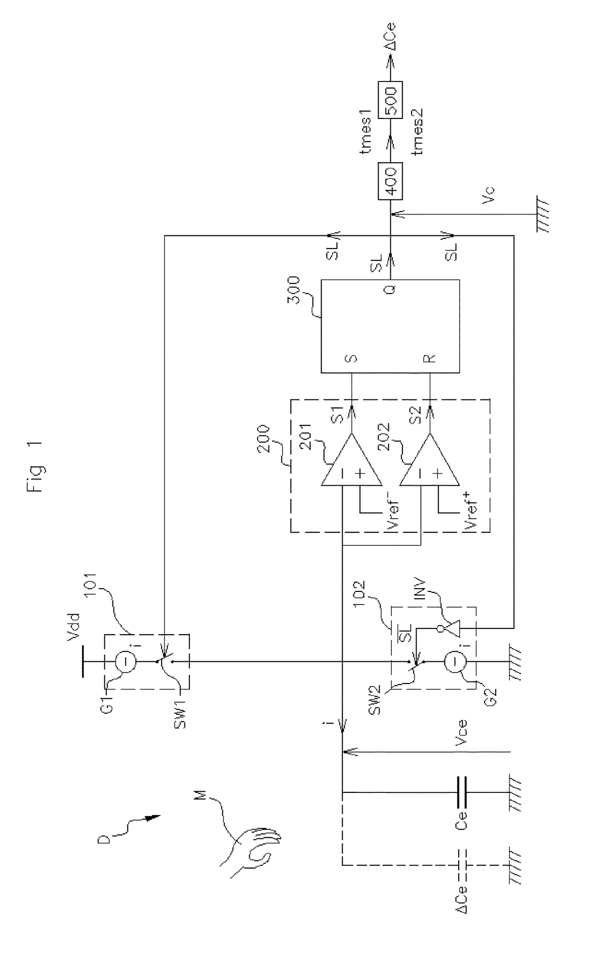
[0143]According to FIG. 3, the measuring device D′ according to the invention furthermore comprises, in addition to the previously described components of the measuring device D of the prior art, an additional capacitance Ca:[0144]a first end of which is electrically connected to the output voltage Vc of the control means 300 and a second end of which is electrically connected to the capacitance Ce,[0145]able to be charged and discharged by the charging 101 and discharging 102 means simultaneously with the charging and discharging of the capacitance Ce.

[0146]Thus, with the measuring device D′ of the invention, when the voltage Vce− (S1=1, S2=0), the control means 300 open the second switch SW2 and close the first switch SW1 in order to simultaneously charge the capacitance Ce and the additional capacitance Ca. This results in a variation of the output voltage Vc of the control means 300. The value of the output voltage Vc of the control means 300 switches over from zero Volts to the...


PUM


Abstract

A method and device for measuring a variation of a capacitance, the device includes: a capacitance having a voltage across its terminals; a charging element and a discharging element; a comparison element; control elements activating the charging element or the discharging element as a function of the value of the voltage across the terminals of the capacitance and of which an output voltage has a high value during the charging and a low value during the discharging; a counter measuring a time representative of a predetermined number of charging and discharging cycles of the capacitance; and an additional capacitance electrically connected to the output voltage and to the capacitance, able to be charged and discharged simultaneously with the charging and discharging of the capacitance.

Description

FIELD OF THE INVENTION[0001]The invention relates to a device for measuring the variation of a capacitance and an associated measuring method. The invention applies more particularly to devices installed on motor vehicle for measuring the variation of a capacitance.BACKGROUND OF THE INVENTION[0002]At present, some motor vehicles are equipped with “hands free” access. This means that the authorized user of the vehicle no longer needs a key in order to open the doors and other openings (bonnet, boot, etc.) of his vehicle. He has instead an identification badge (or remote control) with which the electronic system of the vehicle interacts.[0003]In order to command the opening of a door, for example, the user approaches the door handle. A capacitive presence sensor situated in the handle detects the presence of the user. This sensor is connected to the electronic computer ECU (Electronic Control Unit) of the vehicle and sends it a presence detection signal. The electronic computer of the...

Claims


Application Information

Patent Timeline
Patent Type & Authority Patents(United States)
IPC IPC(8): G01R27/26G06F17/11H03K17/955
CPCG01R27/2605G06F17/11H03K17/955H03K2217/960715
Inventor HOURNE, XAVIER
Owner VITESCO TECH GERMANY GMBH
Why Eureka
Eureka Blog
Learn More