
Slider assembly and zipper comprising same

a sliding assembly and zipper technology, applied in the direction of slide fasteners, applications, accessories, etc., can solve the problems of increasing the initial investment in equipment, inconvenient fastening operation, and difficulty for users to insert the insertion pin into the bottom stop box

Active Publication Date: 2017-07-04
KMK ZIPPER CO LTD
View PDF22 Cites 0 Cited by
  • Summary
  • Abstract
  • Description
  • Claims
  • Application Information

AI Technical Summary

Benefits of technology

The present invention is a zipper comprising two tapes with regular teeth arranged on their sides, a slider that moves along the teeth, a locking unit that prevents the slider from moving backward, and a bottom unit that connects to the locking unit. The locking unit and bottom unit are elastically coupled to each other in a perpendicular direction to the movement plane of the slider. The invention allows for easy and quick disengagement of both tapes with a simple lowering of the slider. The use of a slider and teeth with the same shapes as the existing slider facilitates standardization and optimization of each component and reduces production costs and initial investment in equipment.

Problems solved by technology

However, this conventional zipper has a problem in that the fastening operation is inconvenient.
That is in order to fasten the zipper, a bottom stop insertion pin at an end of the tape, to which the slider is not coupled, should be inserted through the slider into a bottom stop box, and when a user wears gloves, for example, it is difficult for the user to insert the insertion pin into the bottom stop box.
Therefore, the existing slider and teeth cannot be used, and thus it is necessary to build new equipment for manufacturing the slider and teeth, which increases the initial investment in equipment.
Moreover, these teeth have such problems that the process of coupling to the tape is complicated and restrictive, which increases the overall production costs, and the standardization and optimization of each component requires a lot of time and effort.

Method used


Image

  • Slider assembly and zipper comprising same
  • Slider assembly and zipper comprising same
  • Slider assembly and zipper comprising same

Examples


Embodiment Construction

[0047]Hereinafter, preferred embodiments of the present invention will be described in detail with reference to the accompanying drawings. Advantages and features of the present invention and methods of accomplishing the same will become apparent by reference to the following detailed description of preferred embodiments and the accompanying drawings. The present invention may, however, be embodied in many different forms and should not be construed as being limited to the embodiments set forth herein. Rather, these embodiments are provided so that this disclosure will be thorough and complete and will fully convey the concept of the invention to those skilled in the art, and the present invention will only be defined by the appended claims. Like reference numerals refer to like elements throughout the specification.

[0048]The terms used in the present application are merely used to describe particular embodiments, and are not intended to limit the present invention. As used herein, ...


PUM


Abstract

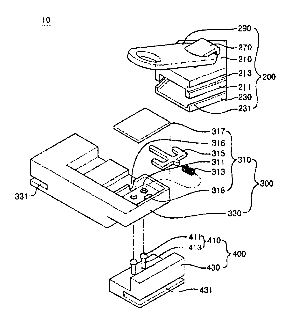
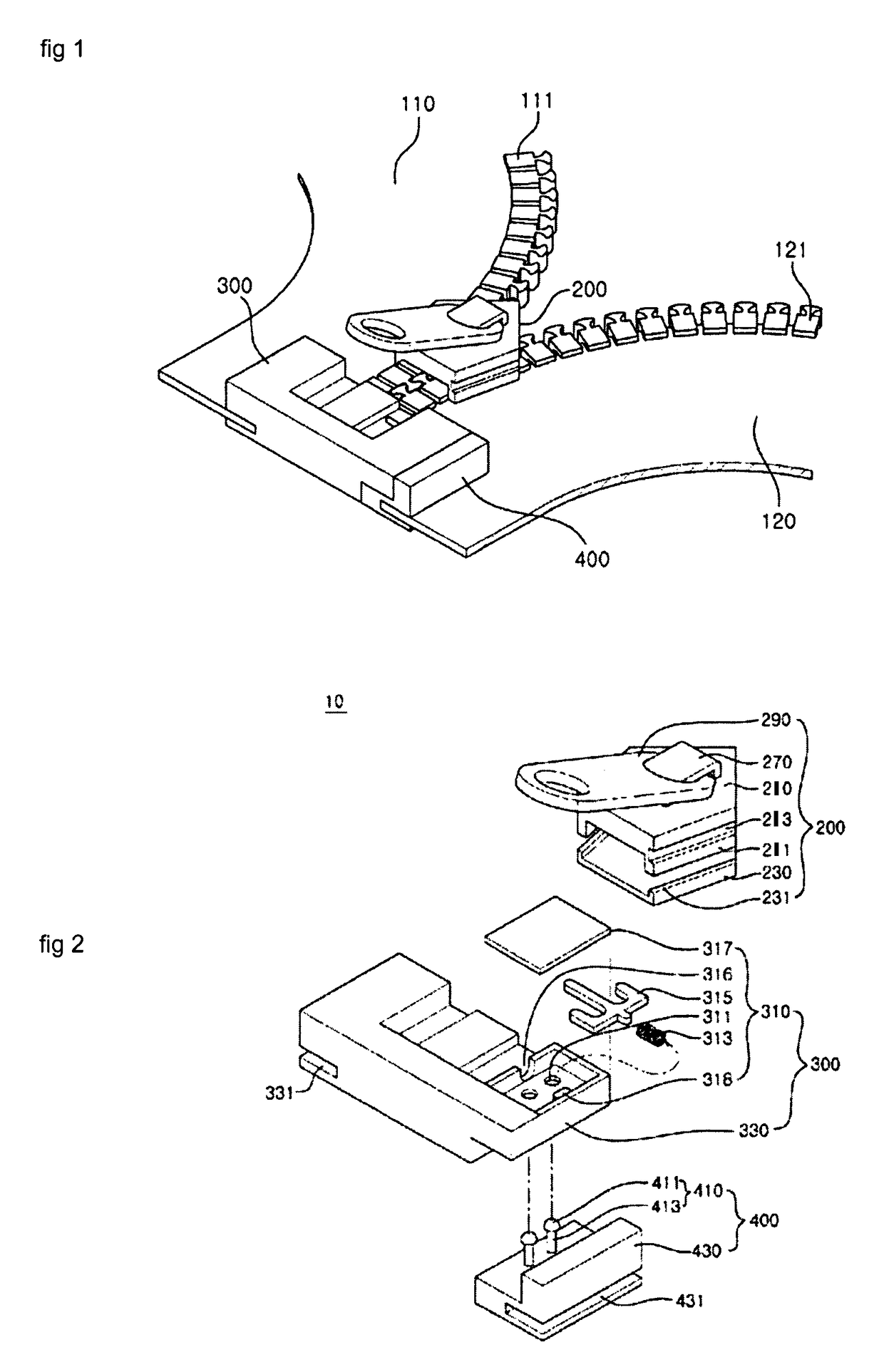
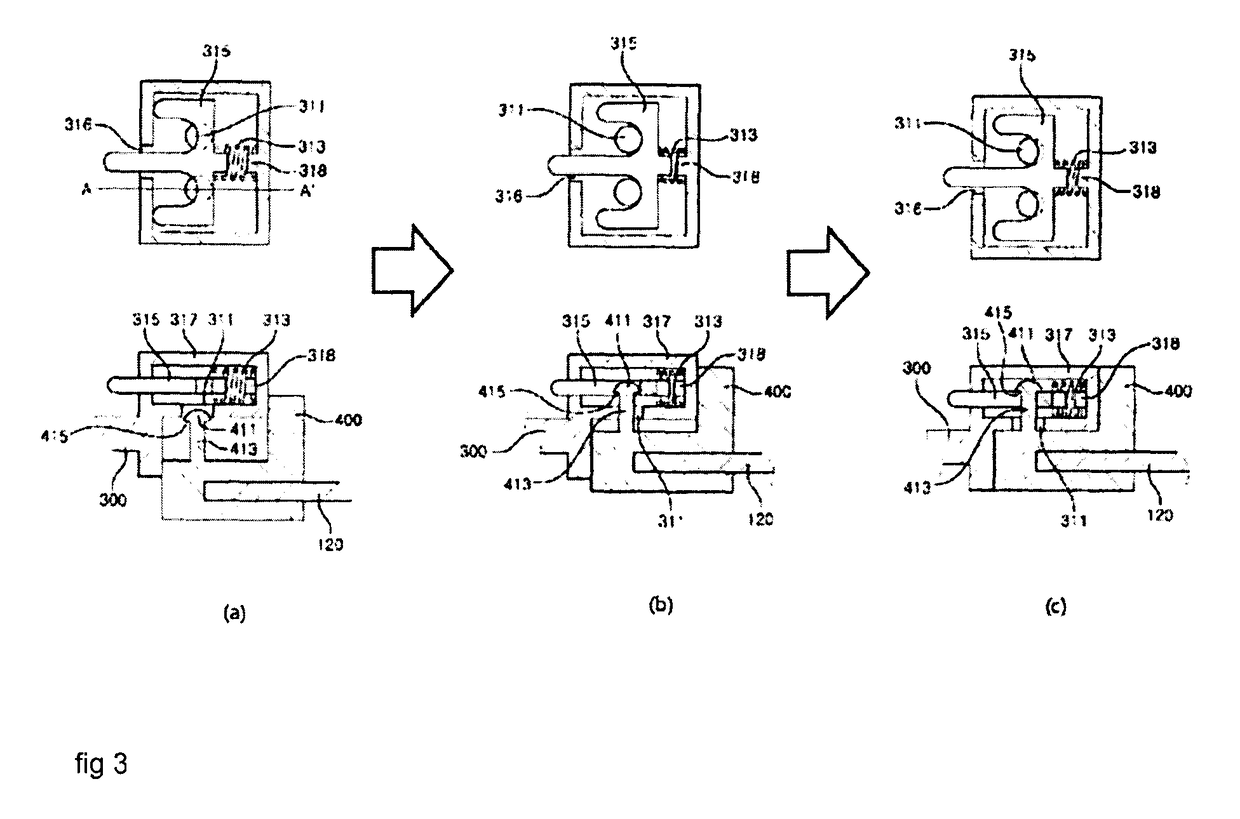
A slider assembly includes: a slider comprising upper and lower plates provided with teeth guides, and a post connecting the upper and lower plates, the slider interlocking the teeth while advancing along the teeth arranged a set distance apart on each sides of first and second tapes; and separating the teeth while moving backwards therealong; a locking unit, disposed at the longitudinal-direction end of the first tape, for restricting the backward movement of the slider; and a bottom unit, disposed at the longitudinal-direction end of the second tape, elastically coupling with the locking unit by the vertical pressure (in the direction of the thickness of the tape) applied by the overlapping locking unit pressing down, and uncoupling therefrom by the force of moving the slider backwards. The slider assembly can be included in a zipper.

Description

REFERENCE TO RELATED APPLICATIONS[0001]This application is a National Stage of International Application No. PCT / KR2013 / 012439, filed Dec. 31, 2013 which claims the benefit of Korean Patent Application No 10-2012-0158548, filed Dec. 31, 2012, each of which is hereby incorporated by reference.TECHNICAL FIELD[0002]The present invention relates to a slider assembly and a zipper comprising the same.BACKGROUND ART[0003]Generally, a zipper is installed in a bag or clothing to open and close an inlet and is widely used due to its easy way to open and close.[0004]The structure of a conventional zipper can be simply defined as follows. Teeth are disposed at regular interval at the opposing sides of a pair of fabric tapes, respectively, and a slider with a structure in which the front and rear sides communicate with each other is coupled to one of the tapes.[0005]When the slider is moved forward, the teeth at both sides enter through the front side of the slider to be engaged with each other ...

Claims


Application Information

Patent Timeline
Patent Type & Authority Patents(United States)
IPC IPC(8): A44B19/36A44B19/30A44B19/02A44B19/38
CPCA44B19/36A44B19/02A44B19/30A44B19/38Y10T24/2513
Inventor LEE, OK-KYUNG
Owner KMK ZIPPER CO LTD
Learn More