Supercharge Your Innovation With Domain-Expert AI Agents!

Nail clipping and cutting device

a cutting device and nail clipping technology, applied in the field of nail clipping and cutting devices, can solve the problems of numerous failures, few people want to put up with the hassle of spend time searching for stray nail clippings, and the tendency of nail clippings to spring away from the nail clipper in any number of unpredictably different directions. , to achieve the effect of convenient manufacture and us

Inactive Publication Date: 2017-07-04
LATORRE SALVATORE +1
View PDF5 Cites 7 Cited by
  • Summary
  • Abstract
  • Description
  • Claims
  • Application Information

AI Technical Summary

Benefits of technology

[0015]An advantage of the present invention is to provide an improved nail clipping device that is easy to manufacture and use my people of all ages.
[0016]Another advantage of the present invention is to provide an improved nail clipping device that collects all nail cuttings and prevents the same from escaping a housing of the nail clipping device.
[0017]Still another advantage of the present invention is to provide an improved nail clipping device with the housing adaptable to engage nail clippers with cutting edges located on a front of the nail clipper or on a side of the nail clipper.
[0018]It is an object of the invention to provide improved elements and arrangements thereof in an apparatus for the purposes described which is inexpensive, dependable and fully effective in accomplishing its intended purposes.
[0019]These and other objects of the present invention will become readily apparent upon further review of the following specification and drawings.

Problems solved by technology

When a person trims his nails, the nail clippings have a tendency to spring away from the nail clipper in any number of unpredictably different directions.
However, few people want to put up with the hassle of and spend time for searching for stray nail clippings.
Many attempts to devise such receptacles have been made over the years but resulted in numerous failings.
The major disadvantage of that design was location of cutting edges along with the edge of the resilient body thereby allowing most of the clipping to escape the resilient body.
However, the nail clippings which are kept from falling away from the nail clipper are unfortunately not ejected away from the clipper opening and into a storage receptacle.
The nail clippings, accumulating at the clipper opening, therefore have the undesired effect of jamming the clipper's cutting means.
This default results in mechanism failure.
Furthermore, Wilson does not disclose any means for easy emptying of the nail clippings.
However, the aforementioned prior art nail clipping devices still need improvements and modifications.

Method used


Image

  • Nail clipping and cutting device
  • Nail clipping and cutting device
  • Nail clipping and cutting device

Examples


Embodiment Construction

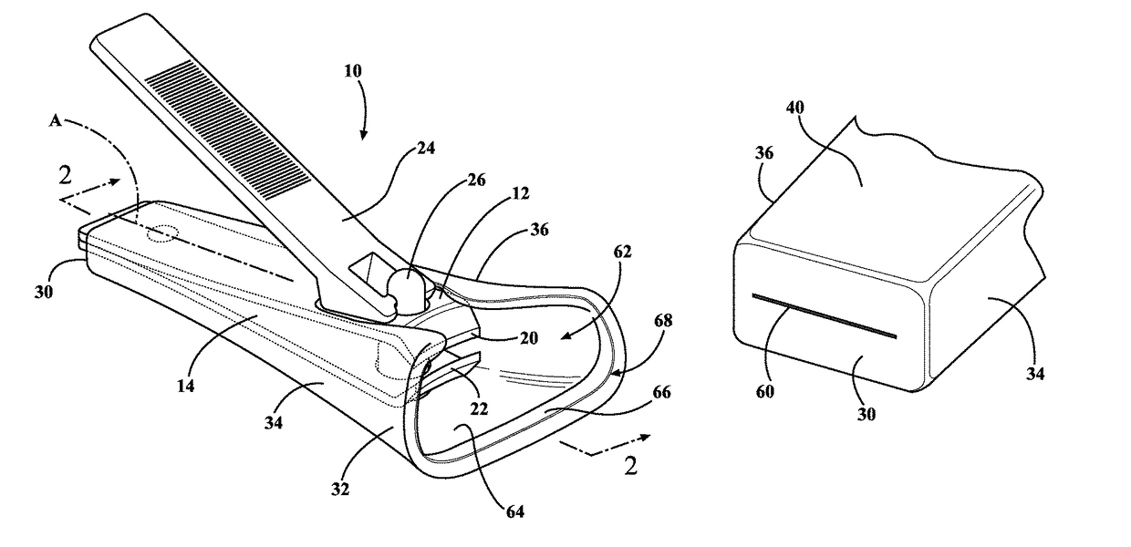
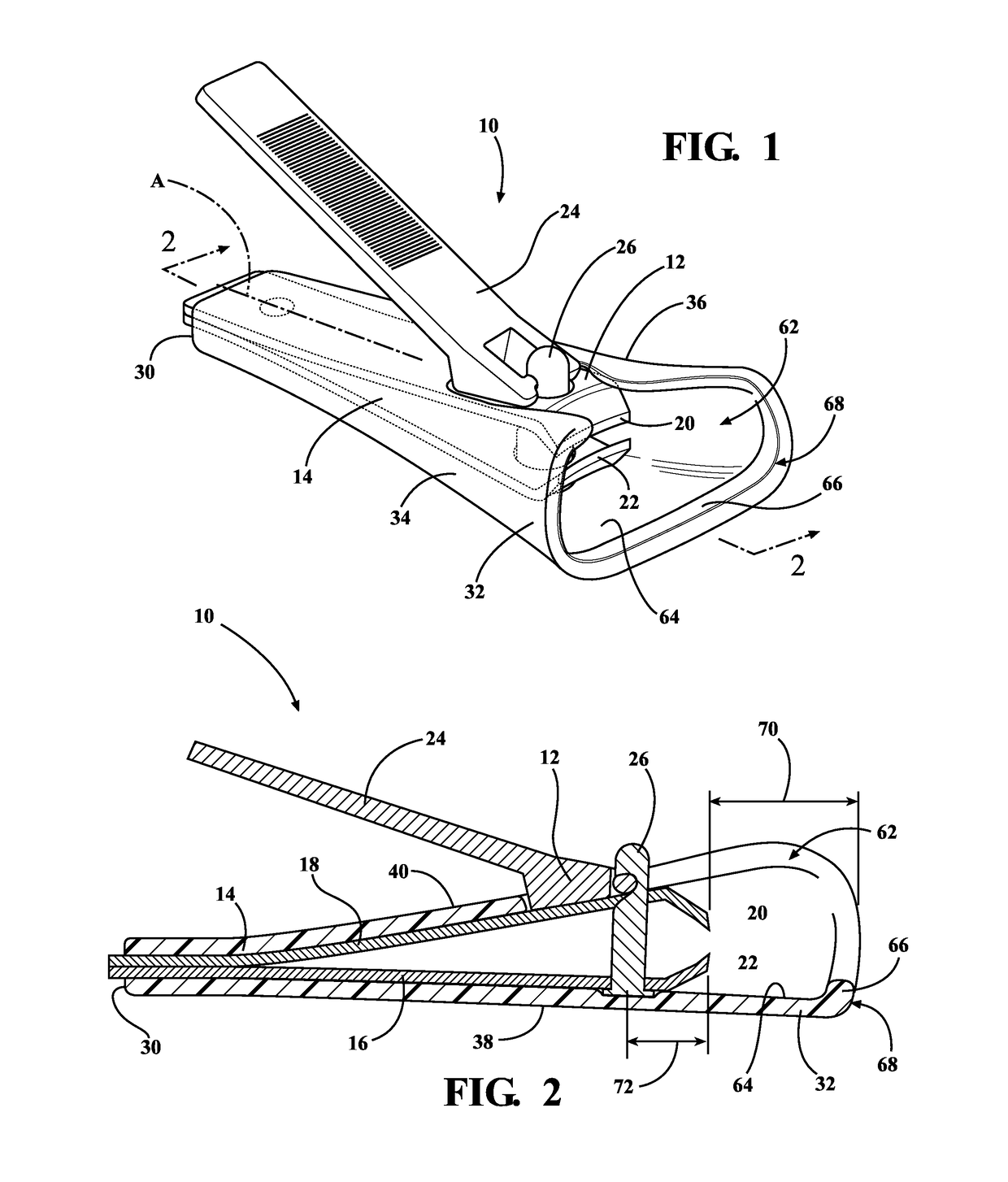
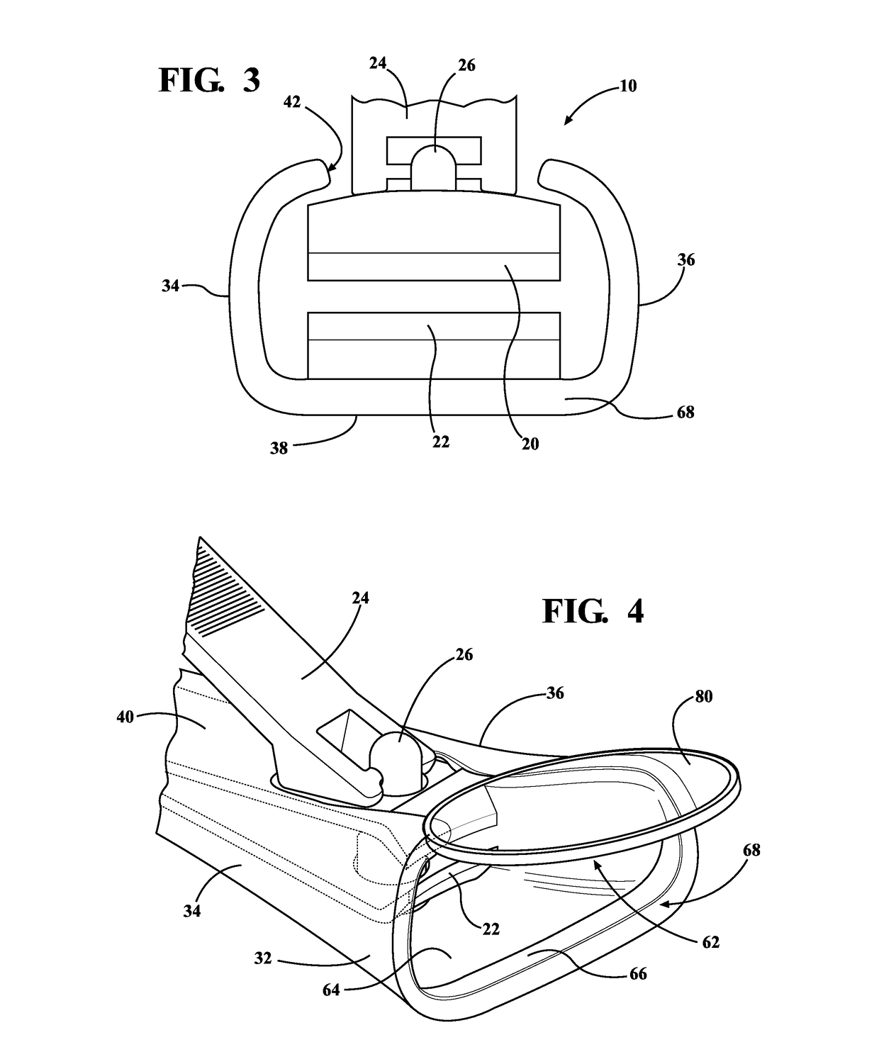
[0031]Referring to FIGS. 1 through 4, 7, and 8 wherein like numerals indicate like or corresponding parts throughout the several views, an apparatus of the present invention is generally shown at 10. Referring to FIGS. 5 through 6, wherein like numerals indicate like or corresponding parts throughout the several views, a second alternative embodiment of the apparatus 10 of the present invention is generally shown at 100. Referring to FIG. 9, wherein like numerals indicate like or corresponding parts, a third alternative embodiment of the apparatus 10 of the present invention is generally shown at 200.

[0032]As shown in FIGS. 1 through 4, 7, and 8, the apparatus 10 of the present invention presents a nail clipping device. The nail clipping device 10 includes a nail clipper 12 and a housing 14 adaptable to receive the nail clipper 12. The nail clipper 12 includes a pair of members or arms 16 and 18 each presenting cutting edges 20 and 22. A lever 24 is mechanically engaged 26 with the ...


PUM


Abstract

A nail clipping device of the present invention presents a nail clipper and a housing adaptable to fit onto the nail clipper. The housing is made of a resilient material having open scoop overhanging cutting portions of the nail clipper for receiving nail clippings. The housing is designed to allow convenient collection and disposal of the nail clippings. The housing includes a magnifying glass connected thereto for better targeting of the nails to be clipped.

Description

RELATED APPLICATIONS[0001]This application incorporates U.S. application Ser. No. 14 / 474,138, filed on Aug. 21 2014, by reference in its entirety.FIELD OF THE INVENTION[0002]The present invention relates to nail clipping and cutting devices and more particularly to nail clippings receptacles having enhancements that improve the receptacle's functionality.BACKGROUND OF THE INVENTION[0003]People of all ages trim and clip nails on daily bases. Nail clippers became a necessity as people cannot get by especially during travel. When a person trims his nails, the nail clippings have a tendency to spring away from the nail clipper in any number of unpredictably different directions. However, few people want to put up with the hassle of and spend time for searching for stray nail clippings. For this reason there is a strongly perceived need for nail clippings receptacles for use with nail clippers. Many attempts to devise such receptacles have been made over the years but resulted in numerou...

Claims


Application Information

Patent Timeline
Patent Type & Authority Patents(United States)
IPC IPC(8): A45D29/02
CPCA45D29/023
Inventor LATORRE, SALVATORESAFIE, JOANNE
Owner LATORRE SALVATORE
Features
  • R&D
  • Intellectual Property
  • Life Sciences
  • Materials
  • Tech Scout
  • Unparalleled Data Quality
  • Higher Quality Content
  • 60% Fewer Hallucinations
Learn More