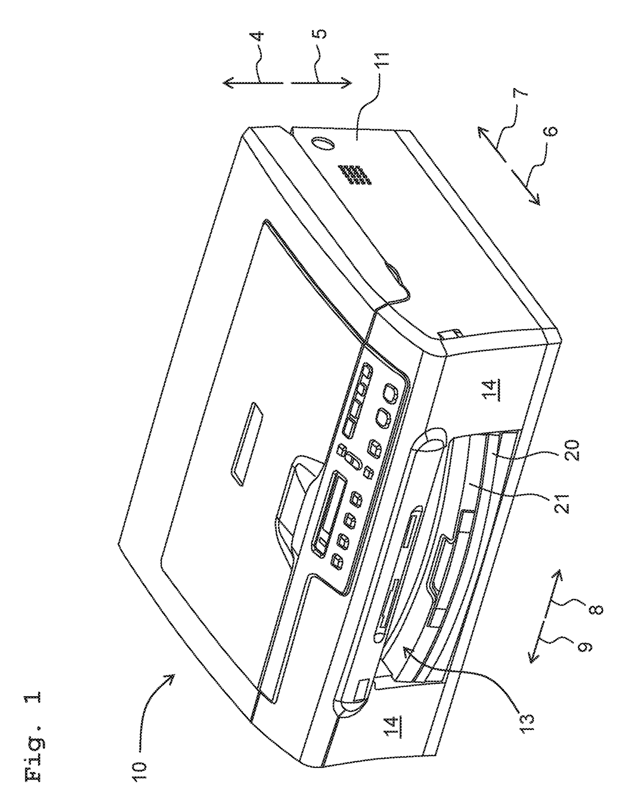
Ink-jet recording apparatus

a recording apparatus and a technology of a recording device, applied in the direction of printing, other printing apparatus, etc., can solve the problems of sheet support, sheet contact with the nozzle, sheet bending or warping, sheet downstream edge portion in the conveyance direction of the sheet in this curved or bent state while being oriented downward, etc., to achieve the effect of suppressing the curving or warping of the sh

Active Publication Date: 2017-07-04
BROTHER KOGYO KK
View PDF10 Cites 2 Cited by
  • Summary
  • Abstract
  • Description
  • Claims
  • Application Information

AI Technical Summary

Benefits of technology

[0006]In this situation, in a case that the ink adheres to the sheet, end portions of the sheet in the width direction thereof are easily curved and easily floated from the platen as compared with a central portion of the sheet in the width direction. Accordingly, in a case of imparting the waved shape along the width direction to the sheet, it is possible to impart such a waved shape that the end portions of the sheet in the width direction become trough (valley, bottom) portions, respectively, of the waved shape. This widens the distance between the nozzles and the end portions of the sheet in the width direction, which in turn makes it possible to lower such a possibility that the sheet might contact the nozzles.
[0017]According to this configuration, the first waved-shape imparting mechanism imparts such a waved shape that the both end portions of the sheet in the width direction become the valley portions of the waved shape (or “are oriented downward”). Accordingly, it is possible to suppress any upward floating of both end portions of the sheet in the width direction, and to lower the possibility that the sheet might contact the recording section.
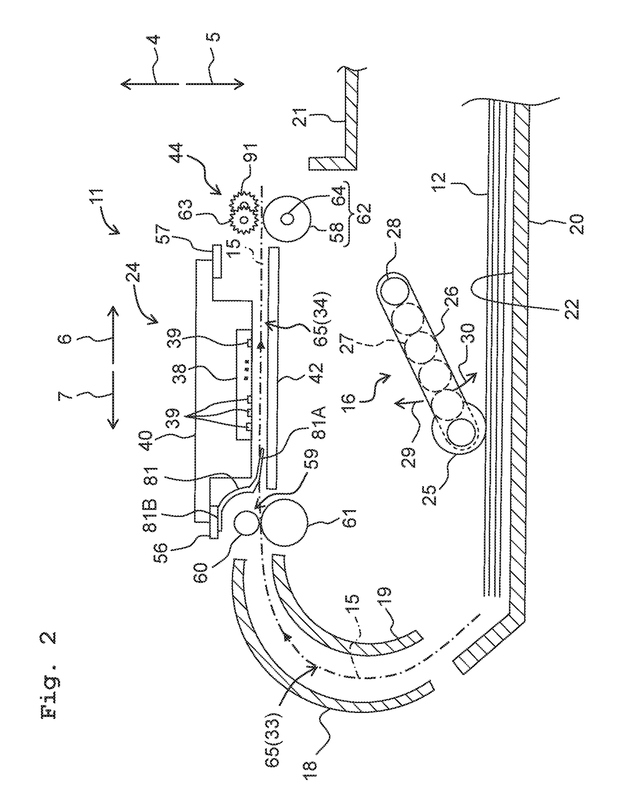
[0018]Further, according to the present teaching, the upstream end portion of the second supporting surface in the conveyance direction is located at the position below the downstream edge portion of the first supporting surface in the conveyance direction. Accordingly, the downstream edge portion of the sheet in the conveyance direction can be located at the position below the first supporting surface in the state that the downstream edge portion of the sheet is supported by the upstream end portion of the second supporting surface in the conveyance direction. As a result, it is possible to suppress the floating, from the first supporting surface, of other portion of the sheet which is different from the downstream edge portion of the sheet in the conveyance direction.
[0020]In view of such a fear, in the present configuration, the second supporting surface is provided with the projections. With this, in the downstream edge portion of the sheet in the conveyance direction, the both end portions in the width direction of the sheet are lifted by the projections. As a result, it is possible to lower such a possibility that in the downstream edge portion of the sheet in the conveyance direction, the both end portions in the width direction of the sheet might be caught by the second supporting surface.
[0021]According to the present teaching, it is possible to suppress the curving or warping of the sheet supported by the platen.

Problems solved by technology

Further, there is such a fear that the downstream edge portion in the conveyance direction of the sheet in this curved or bent state while being oriented downward might be caught by the rib, etc.
Furthermore, in a case that the sheet is conveyed in such a state that the downstream edge portion of the sheet in the conveyance direction is still caught by the ribs, etc., there is such a fear that the curving (warping, bending, curling) of the sheet might become great and the sheet might contact the nozzles.
Then there is such a fear that the both end portions in the width direction of the sheet, in the downstream edge portion of the sheet in the conveyance direction, might be caught by the second supporting surface.

Method used


Image

  • Ink-jet recording apparatus
  • Ink-jet recording apparatus
  • Ink-jet recording apparatus

Examples


modified embodiment

[0113]In the above-described embodiment, the projections 90 have the rib shape. It is allowable, however, that the projections 90 do not have the rib shape. For example, it is allowable that the length of the projections 90 in the right and left directions 8 and 9 are not less than the length of the projections 90 along the conveyance direction 15.

[0114]Further, the configuration of the projections 90 is not limited to the configuration as depicted in FIG. 5.

[0115]For example, it is allowable that the projections 90 are provided only on the flat surface 84A and the inclined surface 84B, and not provided on the flat surface 84C, as depicted in FIGS. 7A to 7C.

[0116]Further, in the embodiment, the upper surface 90A is inclined upward toward the conveyance direction 15; and the angle θ1 is greater than the angle θ2 as depicted in FIG. 5. However, it is allowable that the upper surface 90A is parallel to the inclined surface 84B, as depicted in FIG. 7A. Namely, the angle defined between ...


PUM


Abstract

An ink-jet recording apparatus includes: a roller; a first supporting member; a recording section; a second supporting member; and a first waved-shape imparting mechanism configured to impart, to the sheet, the waved shape so that both end portions of the sheet in the width direction are oriented downward. An upstream end portion, of the second supporting surface, in the conveyance direction is located below a downstream end portion of a first supporting surface of the first supporting member in the conveyance direction. The second supporting surface of the second supporting member is formed with projections arranged respectively at locations, of the second supporting surface, at which the both end portions of the sheet in the width direction are supported, the projections projecting upward above a location of the second supporting surface at which a central portion of the sheet in the width direction is supported.

Description

CROSS REFERENCE TO RELATED APPLICATION[0001]The present application claims priority from Japanese Patent Application No. 2015-195474 filed on Sep. 30, 2015 the disclosure of which is incorporated herein by reference in its entirety.BACKGROUND[0002]Field of the Invention[0003]The present invention relates to an ink-jet recording apparatus configured to record an image, etc. on a sheet by discharging ink droplets of an ink from nozzles provided on a recording unit of the ink-jet recording apparatus.[0004]Description of the Related Art[0005]Conventionally, there is known an ink-jet recording apparatus which jets ink droplets from nozzles onto a sheet so as to record an image, etc. on the sheet. In the ink-jet recording apparatus, there is a publicly known configuration wherein a waved state is imparted to a sheet in order to suppress any floating of the sheet from a platen accompanying with deformation of the sheet due to the ink adhered thereto (phenomenon known as “cockling” of the s...

Claims


Application Information

Patent Timeline
Patent Type & Authority Patents(United States)
IPC IPC(8): B41J13/10B41J11/04B41J2/01
CPCB41J11/04B41J2/01B41J11/00B41J11/057B41J11/005
Inventor ITO, TSUYOSHISANO, IWANEKANAZAWA, GAKURO
Owner BROTHER KOGYO KK
Why Eureka
Try Eureka