Vertical takeoff and landing unmanned aerial vehicle

a technology of unmanned aerial vehicles and vertical landings, which is applied in the direction of vertical landing/take-off aircraft, canard-type aircraft, transportation and packaging, etc., can solve the problems of essentially dead weight of lift fans and their associated components, reducing the overall efficiency of aircraft, and reducing the aerodynamic efficiency of aircra

Active Publication Date: 2017-07-04
KING SAUD UNIVERSITY
View PDF18 Cites 30 Cited by
  • Summary
  • Abstract
  • Description
  • Claims
  • Application Information

AI Technical Summary

Benefits of technology

[0011]These and other features of the present invention will become readil

Problems solved by technology

The addition of VTOL capability, however, typically decreases the overall efficiency of the aircraft, both through added weight as well as by making the aerodynamics of the aircraft less efficient.
During horizontal flight, the lift fan and its associated components are essentially dead weight.
Further, if the lift fan and its associated components are not stored away in the fuselage, they tend to increase drag on the aircraft.
However, tiltrotors can only takeoff and land vertically, since they use very large propellers whose diameters are larger than the ground clearance.
Further, an aircraft wi

Method used


Image

  • Vertical takeoff and landing unmanned aerial vehicle
  • Vertical takeoff and landing unmanned aerial vehicle
  • Vertical takeoff and landing unmanned aerial vehicle

Examples


Embodiment Construction

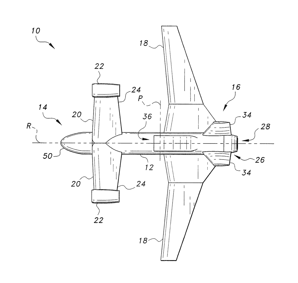
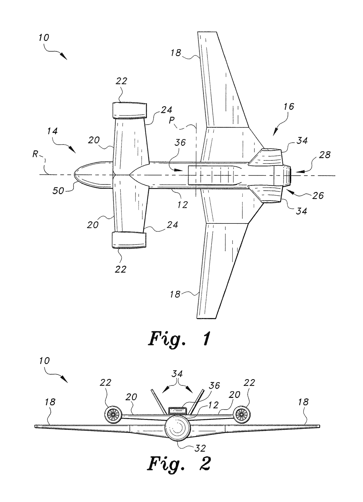
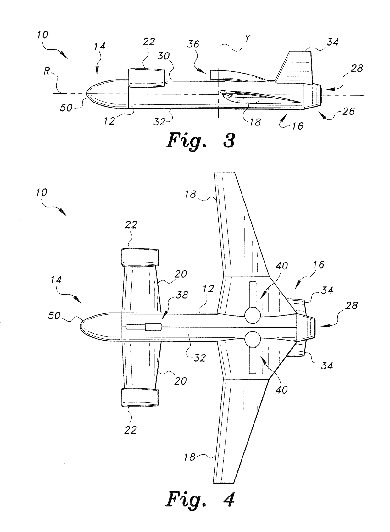
[0019]As shown in FIGS. 1-4, the vertical takeoff and landing (VTOL) unmanned aerial vehicle (UAV) 10 includes a pair of selectively rotatable ducted fans 22 and a selectively rotatable thrust vectoring nozzle 28 to provide vertical takeoff and landing for the unmanned aerial vehicle 10. The vertical takeoff and landing unmanned aerial vehicle 10 includes a fuselage 12 having a top end 30, a bottom end 32, and opposed forward and rear portions 14, 16, respectively. The fuselage 12 is elongated along a roll axis R thereof. A pair of fixed forward-swept wings 18 are mounted on the rear portion 16 of the fuselage 12, and a pair of canards 20 are mounted on the top end 30 of the forward portion 14 of fuselage 12. A V-shaped stabilizer 34 is further mounted on the top end 30 of the rear portion 16 of the fuselage 12, as is conventionally known.

[0020]The pair of ducted fans 22 are respectively mounted on free ends 24 of the pair of canards 20. The ducted fans 22 are selectively rotatable ...


PUM


Abstract

The vertical takeoff and landing unmanned aerial vehicle includes a pair of selectively rotatable ducted fans and a selectively rotatable thrust vectoring nozzle providing vertical takeoff and landing for an unmanned aerial vehicle or a similar type of aircraft. A pair of fixed forward-swept wings are mounted on a rear portion of a fuselage, and a pair of canards are mounted on a top end of a forward portion of the fuselage. The pair of ducted fans are respectively mounted on free ends of the pair of canards, and are selectively rotatable about an axis parallel to a pitch axis of the fuselage. An engine is mounted in the rear portion of the fuselage, and a thrust vectoring nozzle is mounted on the rear portion of the fuselage for directing thrust exhaust from the engine. The thrust vectoring nozzle is selectively rotatable about an axis parallel to the pitch axis.

Description

BACKGROUND OF THE INVENTION[0001]1. Field of the Invention[0002]The present invention relates to unmanned aerial vehicles (UAVs), and particularly to a vertical takeoff and landing UAV.[0003]2. Description of the Related Art[0004]A wide variety of aircraft designs for achieving vertical takeoff and landing (VTOL) exist. The addition of VTOL capability, however, typically decreases the overall efficiency of the aircraft, both through added weight as well as by making the aerodynamics of the aircraft less efficient. A typical VTOL aircraft is configured similar to a conventional aircraft, but with an added lift fan in most cases. The lift fan may be in communication with the aircraft engine or may be separately powered. The additional lift fan is commonly used in addition to tilting main propellers or jet nozzles such that the combination of the lift fan and the tilting main propellers or jet nozzles produces a vertical lifting force. Once the aircraft is hovering, the main rotors / noz...

Claims


Application Information

Patent Timeline
IPC IPC(8): B64C29/00B64C5/06B64C25/10B64C39/02B64C39/08
CPCB64C29/00B64C39/08B64C39/024B64C25/10B64C5/06B64C2201/042B64C2201/162B64C2201/104B64C29/0075B64C39/12B64U50/12B64U70/80B64U30/10B64U10/25B64U70/60B64U50/14B64U50/19
Inventor SADEK, SHEREEF ALY
Owner KING SAUD UNIVERSITY
Why Eureka
Try Eureka