3D projection system using laser light sources

a laser light source and projection system technology, applied in optics, instruments, electrical equipment, etc., can solve the problems of inconvenient programming, inconvenient use, and inability to project and view 3d and 2d wide color gamut solutions, and achieve the effect of convenient implementation in programming

Active Publication Date: 2017-07-04
DOLBY LAB LICENSING CORP
View PDF26 Cites 7 Cited by
  • Summary
  • Abstract
  • Description
  • Claims
  • Application Information

AI Technical Summary

Benefits of technology

[0014]Portions of the invention may be conveniently implemented in programming on a general purpose computer, or networked computers, and the results may be displayed on an output device connected to any of the general purpose, networked computers, or transmitted to a remote device for output or display. In addition, any components of the present invention represented in a computer program, data sequences, and / or control signals may be embodied as an electronic signal broadcast (or transmitted) at any frequency in any medium including, but not limited to, wireless broadcasts, and transmissions over copper wire(s), fiber optic cable(s), and co-ax cable(s), etc.

Problems solved by technology

This method works best for black and white original images, and is not well suited for color images.
It has several problems, these include the need for a silver screen which is expensive, fragile, and not uniform.
Another problem is that the viewer must keep his head oriented vertically to avoid crosstalk from one eye to another.
Since having a direct wired connection to the Glasses in a theatre is impractical, a wireless or infrared signaling method is used to provide a timing reference for the left / right eye shuttering.
The Shutter Glasses are expensive and hard to clean, require batteries that must be frequently replaced, and are limited in their switching rate.
Shutter glasses are only practical for use with D-Cinema or other electronic projection systems since very few film projectors provide the signal required to synchronize the shutter glasses with the frame rate.

Method used


Image

  • 3D projection system using laser light sources
  • 3D projection system using laser light sources
  • 3D projection system using laser light sources

Examples


Embodiment Construction

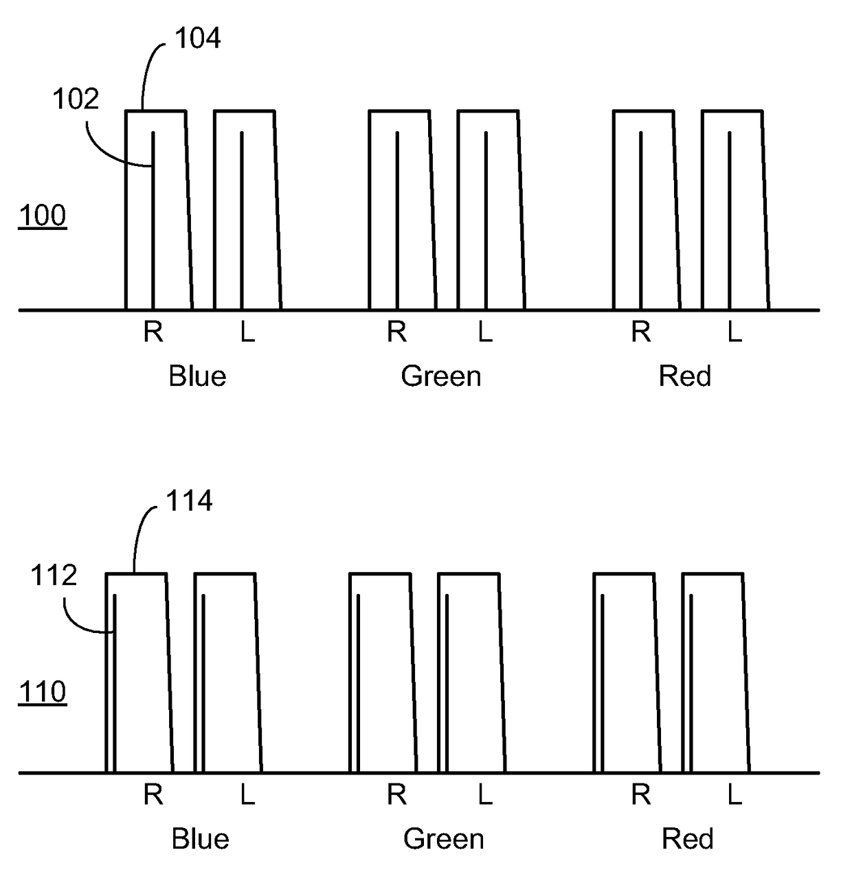
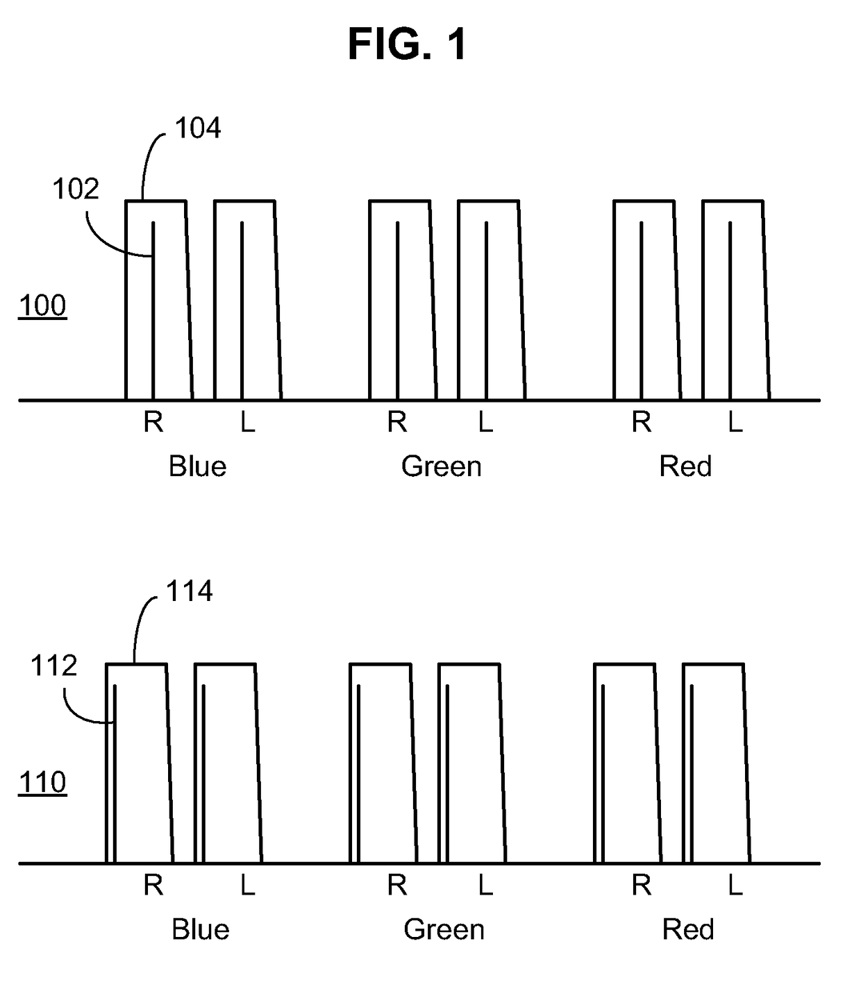
[0027]Referring now to the drawings, wherein like reference numerals designate identical or corresponding parts, and more particularly to FIG. 1 thereof, laser / narrowband lighting and viewing passbands according to embodiments of the present invention are illustrated. A first set of narrowband lights and passbands 100 include blue, green, and red light sources (represented by, for example, narrowband blue light 102) for each of first and second channels of a 3D image generation system. The narrowband lights are, for example, individual lasers or other narrowband light sources. The lights may be produced from a wideband light source or a series of narrower light sources coupled with appropriate filtering to match the desired bandwidth. In one embodiment, the narrowband light sources each comprise multiple closely spaced (or partially overlapping) laser lights that make a contiguous narrowband light source whose output is passed by a corresponding filter. In some embodiments, each lig...


PUM


Abstract

Laser or narrow band light sources are utilized to from left (R1, G1, B1) and right (R2,G2;B2,) images of a 3D projection. Under off-axis viewing of projections (i.e. oblique incident angles) the passbands of the viewing filters in the glasses are blue-shifted, which has the potential of cause crosstalk and / or loss of energy / brightness in any channel or color. This blue-shift is compensated via the combined use of any of viewing passbands (220) encompassing the associated projected lightband (222) and a red-shift passband (224) selection of passband wavelengths that maximize usability of the passband as it “shifts” due to varying or increasing angles of off-axis viewing), curvature of viewing filters, and guard bands between light bands of adjacent channels. Implemented with any number of light sources, additional light sources are utilized to affect a desirable increase in color gamut.

Description

CROSS-REFERENCE TO RELATED APPLICATIONS[0001]This application claims priority to U.S. Provisional Patent Application No. 61 / 452,638 filed 14 Mar. 2011, which is incorporated herein by reference in its entirety.BACKGROUND OF THE INVENTION[0002]The present invention relates to display and viewing systems and more particularly to cinema systems for projecting and viewing 3D and 2D wide color gamut solutions.[0003]Methods for 3D stereoscopic projection include Anaglyph, Linear Polarization, Circular Polarization, Shutter Glasses, and Spectral Separation. Anaglyph is the oldest technology, and provides left / right eye separation by filtering the light through a two color filter, commonly red for one eye, and cyan for the other eye. At the projector, the left eye image is (commonly) filtered through a red filter, and the right image filtered through a cyan filter. The eyewear consists of a red filter for the left eye, and a cyan filter for the right eye. This method works best for black an...

Claims


Application Information

Patent Timeline
Patent Type & Authority Patents(United States)
IPC IPC(8): G02B27/22H04N13/04H04N13/363
CPCG02B27/2228G02B27/2207H04N13/0422H04N13/0431H04N13/0459G02B30/23H04N13/363H04N13/324H04N13/334G02B30/34
Inventor RICHARDS, MARTIN J.
Owner DOLBY LAB LICENSING CORP
Why Eureka
Try Eureka