Light emitting device

a technology of light emitting device and light diffusion material, which is applied in the direction of semiconductor devices, basic electric elements, electrical apparatus, etc., can solve the problems of reducing light outgoing efficiency of light diffusion materials, and achieve the effect of reducing color unevenness and high light outgoing efficiency

Active Publication Date: 2017-07-04
NICHIA CORP
View PDF24 Cites 1 Cited by
  • Summary
  • Abstract
  • Description
  • Claims
  • Application Information

AI Technical Summary

Benefits of technology

[0012]A light emitting device that can reduce color unevenness and has high light outgoing efficiency can be provided by the aforementioned features in this disclosure.

Problems solved by technology

However, in the case where light diffusion materials are used, there may be a problem that the light diffusion materials reduce light outgoing efficiency.

Method used


Image

  • Light emitting device
  • Light emitting device
  • Light emitting device

Examples


embodiment (

EMBODIMENT(S)

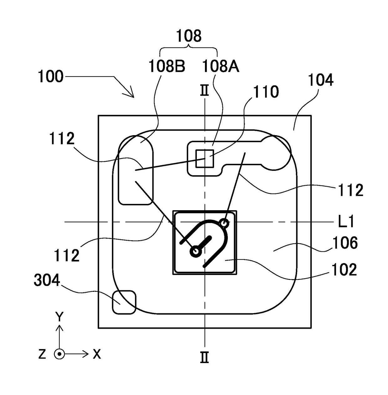
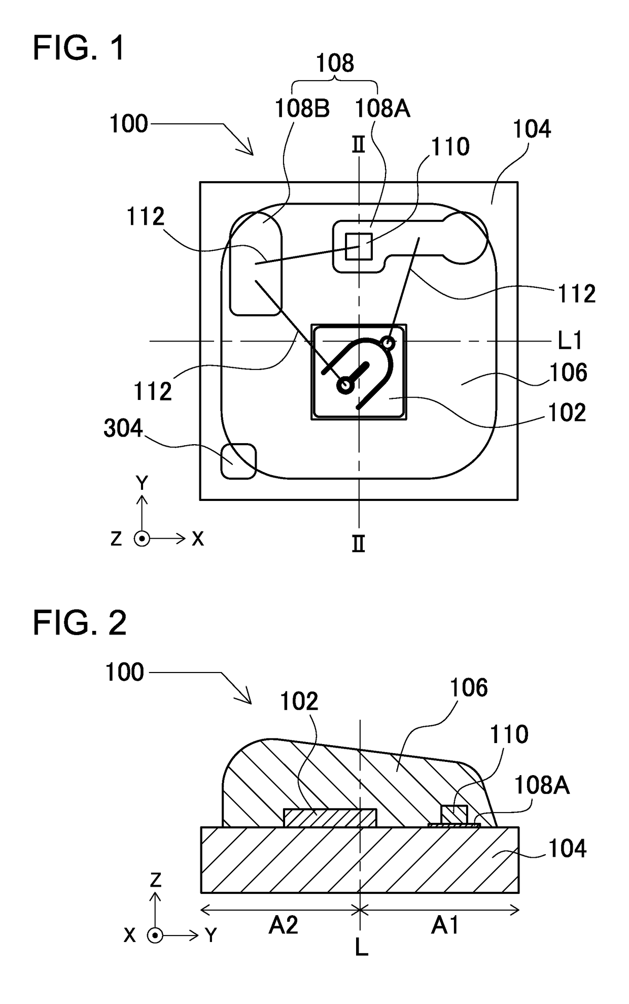
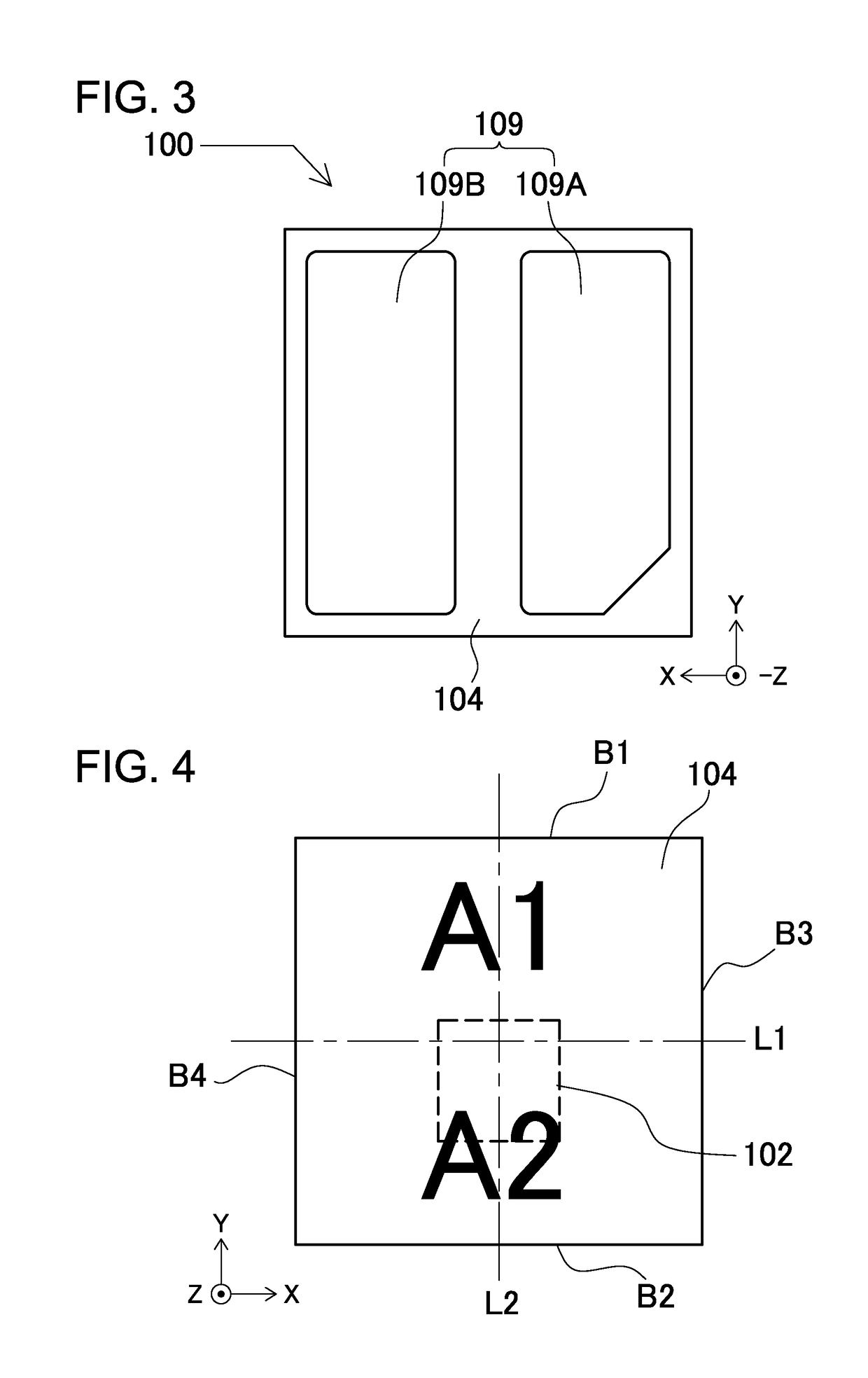
[0021]FIG. 1 is a schematic top view showing a light emitting device 100 according to an embodiment of the present invention. FIG. 2 is a schematic cross-sectional view of the light emitting device taken along the line II-II shown in FIG. 1. FIG. 3 is a schematic bottom view of the light emitting device shown in FIG. 1.

[0022]The light emitting device 100 according to the embodiment of the present invention includes a base member 104 that includes a wiring portion 108, a light emitting element 102 that is arranged on or above the base member 104, and a sealing member 106 that covers the light emitting element 102 and includes a wavelength conversion member.

[0023]The base member 104 serves as a mount member on which the light emitting element 102 is mounted. The wiring portion 108, which is arranged on the surface of the base member 104, is constructed of electrically-conductive members for supplying electric power to the light emitting element 102. The wiring portion 108...


PUM


Abstract

A light emitting device includes a base member, a light emitting element, and a sealing member. The substrate includes a wiring portion. The element is arranged on or above the substrate. The sealing member covers the element, and at least a part of the substrate. The sealing member includes a wavelength conversion member. The part of the substrate is divided into first and second sections by a straight line that passes through the center of the part as viewed in plan view. The wiring portion is arranged so that its area on the first section side is larger than on the second section side. The element is arranged so that its area in the second section is larger than the first section. The height of the sealing member on the second section side is greater than on the first section side.

Description

CROSS-REFERENCE TO RELATED APPLICATIONS[0001]The present application claims priority under 35 U.S.C. §119 to Japanese Patent Application No. 2014-67,685 filed on Mar. 28, 2014, and Japanese Patent Application No. 2015-007975 filed on Jan. 19, 2015. The contents of these applications are incorporated herein by references in their entirety.BACKGROUND OF THE INVENTION[0002]1. Field of the Invention[0003]This disclosure relates to a light emitting device.[0004]2. Description of the Related Art[0005]Light emitting devices for emitting white light are known which include a light emitting element that emits blue light, and a fluorescent material that is excited by absorbing a part of the blue light and emits light with a wavelength longer than the blue light.[0006]It is required for these light emitting devices to provide uniform color tone in all light emitting directions, and to increase luminous intensity.[0007]For example, International Publication No. WO 2013-011,628 A1 discloses a li...

Claims


Application Information

Patent Timeline
Patent Type & Authority Patents(United States)
IPC IPC(8): H01L33/62H01L33/52H01L33/50H01L33/48H01L33/54
CPCH01L33/507H01L33/483H01L33/505H01L33/52H01L33/54H01L33/62H01L2224/45144H01L2224/49171H01L2224/97H01L2924/181H01L2924/1815H01L2933/005H01L2933/0033H01L2933/0041H01L2933/0066H01L2924/00012H01L2924/00H01L33/486H01L33/58
Inventor AMO, TAKAHIRO
Owner NICHIA CORP
Why Eureka
Try Eureka