Suspension device

a technology of suspension device and suspension plate, which is applied in the direction of connection contact material, connection device connection, show hanger, etc., can solve the problem of lack of flexibility and achieve the effect of reducing the amount of ligh

Inactive Publication Date: 2017-07-11
SWEIN ANDREAS +1
View PDF17 Cites 48 Cited by
  • Summary
  • Abstract
  • Description
  • Claims
  • Application Information

AI Technical Summary

Benefits of technology

[0016]The rear wall is preferably angled to minimise the amount of light reflected back out of the profile rail. This in turn provides a visually darkened profile rail passage when viewed from the front opening. The front opening is preferably tapered leading into the passage.
[0017]The lower arm preferably includes one or more sections creating the base contact surface that are located towards the front of the passage. The upper contact surfaces are preferably located toward the rear of the passage. Therefore a plug in element is held in a cantilevered fashion. Rearward of the base contact surface, the internal surface of the lower arm may slope downwardly towards the rear wall. This construction can assist in the insertion and removal of a cantilevered plug in element, with the upper arm preferably having a section defining an elevated ceiling contact surface in front of the upper contact surfaces. This allows for a plug in element to be presented in a upwardly angled orientation and then lowered to substantially horizontal when inserted, and conversely lifted for removal.

Problems solved by technology

However, known systems require a specific corresponding engagement member on the end of the support for insertion into the opening, and lack a certain degree of flexibility.

Method used


Image

  • Suspension device
  • Suspension device
  • Suspension device

Examples


Embodiment Construction

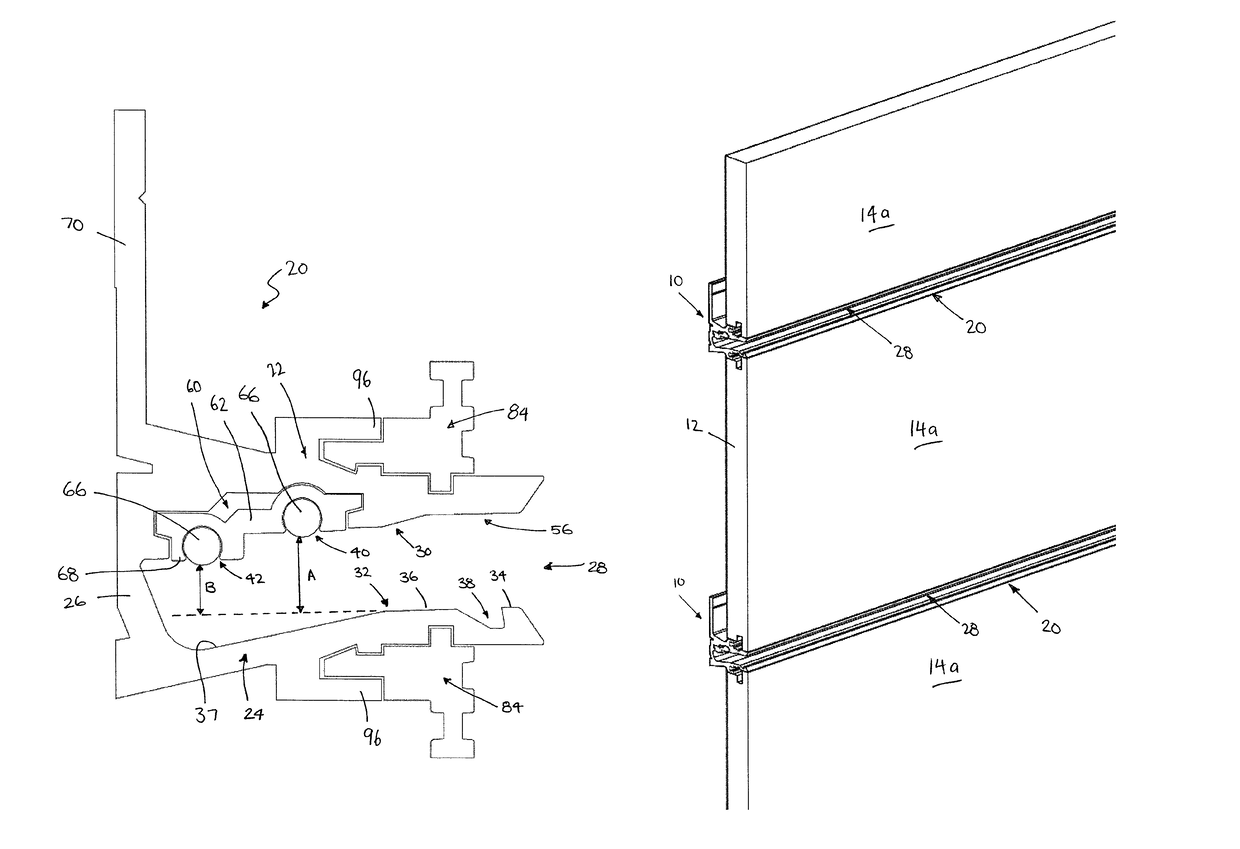
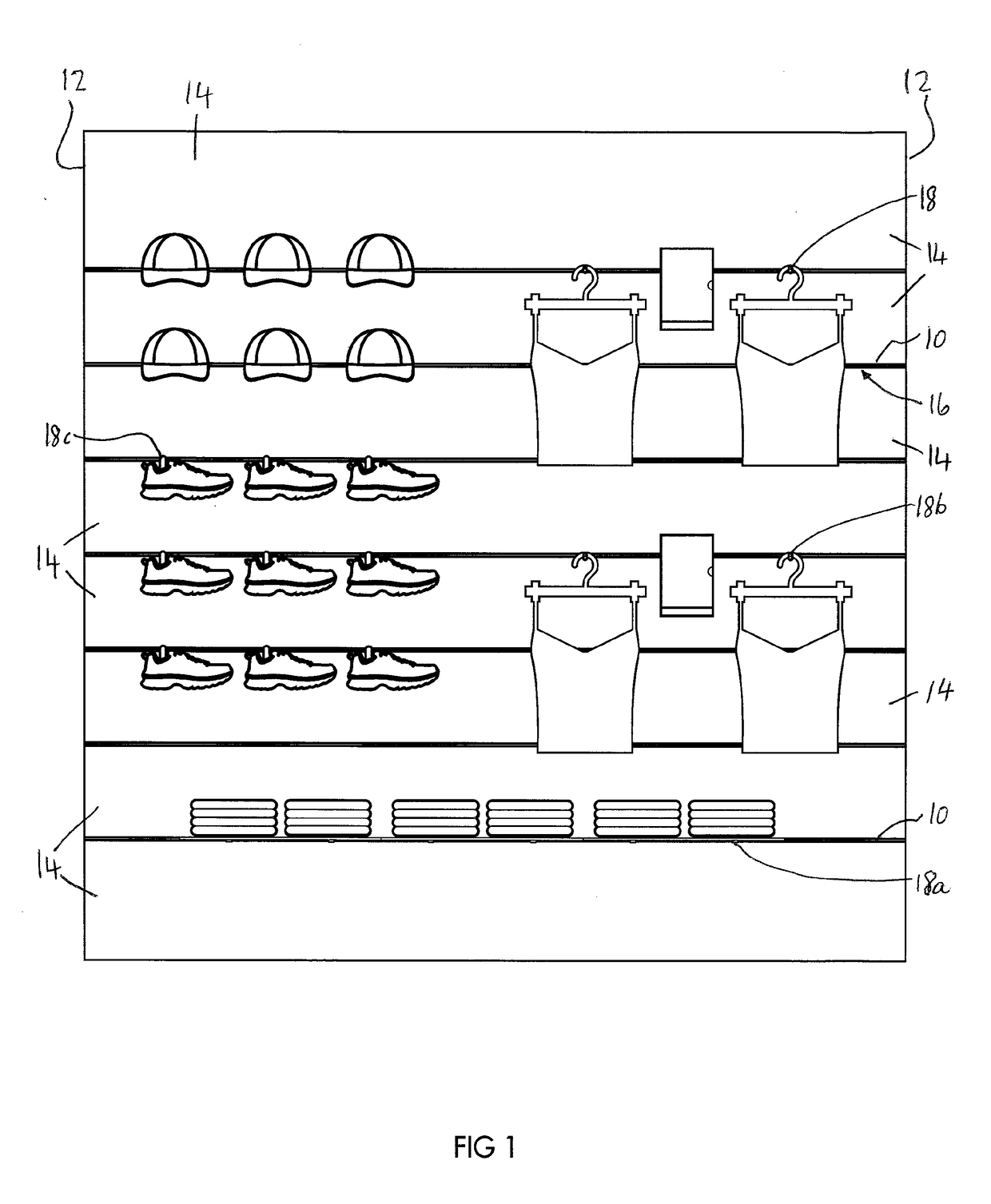
[0092]A merchandising display system is shown in FIG. 1, and includes a plurality of vertically spaced apart suspension devices 10 that extend substantially horizontally and have a length that is continuous to the edges 12 of the display. The plurality of horizontal suspension devices 10 are spaced apart by vertically oriented wall sections 14; the suspension devices 10 and wall sections 14 together forming a vertical wall surface. The suspension devices 10 each include a passage 16 into which plug in elements 18 can be inserted and suspended for use in the display of goods. The plug in elements 18 may be, for example, shelves 18a for goods to be placed on, arms 18b for hangers to suspend from, or hooks 18c for goods to hang off. Any configuration of plug in element is contemplated.

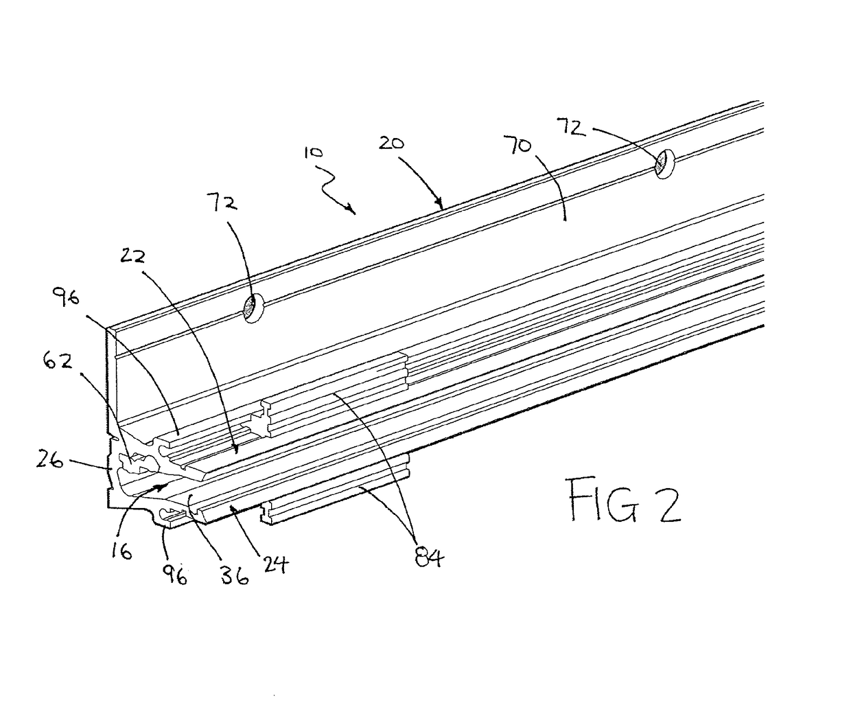
[0093]The suspension device includes a substantially horizontally oriented profile rail section 20. FIGS. 2 and 3, 4 to 6 and 7 illustrate three alternative profile rail sections, the differences to be de...


PUM


Abstract

A suspension device for receiving plug in elements used for the display of goods includes a substantially horizontally oriented profile rail section having an upper arm, a lower arm and a rear wall defining a passage with a front opening into which the plug in elements are inserted. The upper arm defines a ceiling of the passage and the lower arm defines a base of the passage. The base of the passage includes a base contact surface upon which a plug in element rests. The ceiling of the passage includes a stepped profile defining at least two upper contact surfaces that the top of the plug in elements may contact, such that the vertical distances between the base contact surface and the respective upper contact surfaces differ, whereby plug in elements of at least two different thicknesses can be accommodated and suspended within the passage.

Description

FIELD OF THE INVENTION[0001]The present invention relates to a suspension device for receiving plug in elements, such as arms and shelving components, for the display of goods. The present invention finds particular, though not exclusive, application in a retail display environment.BACKGROUND OF THE INVENTION[0002]In retail stores, clothing and goods for sale are typically presented on display arms or shelving units that generally form part of a standalone display stand or are mounted on walls or other large display units.[0003]Garments for example are typically hung from hangers, which are then suspended from the arms. The arms are either straight poles or are equipped with dividers to space out the hangers and garments to ensure all garments are visible. Other items, such as folded apparel, are generally presented on shelving. Shelving is used for the display of many non-hangable items.[0004]In retail environments, it is often desirable to change the way in which items are present...

Claims


Application Information

Patent Timeline
Patent Type & Authority Patents(United States)
IPC IPC(8): A47F5/08H01R25/14H01R4/64A47F7/00
CPCA47F5/0853H01R4/64H01R25/14A47B2220/0075
Inventor KEYVANLOO, AYDIN
Owner SWEIN ANDREAS
Why Eureka
Try Eureka