Method and apparatus for fabrication and tuning of grating-based differential phase contrast imaging system

a technology of contrast imaging and grating, applied in the field of differential phase contrast imaging, can solve the problem of 0.17% dimension change being difficult to realiz

Active Publication Date: 2017-07-11
CARESTREAM HEALTH INC
View PDF64 Cites 21 Cited by
  • Summary
  • Abstract
  • Description
  • Claims
  • Application Information

AI Technical Summary

Problems solved by technology

When the periods of G1 and G2 are in the order of just few micrometers the 0.17% change in dimension may be difficult to realize.

Method used


Image

  • Method and apparatus for fabrication and tuning of grating-based differential phase contrast imaging system
  • Method and apparatus for fabrication and tuning of grating-based differential phase contrast imaging system
  • Method and apparatus for fabrication and tuning of grating-based differential phase contrast imaging system

Examples


Embodiment Construction

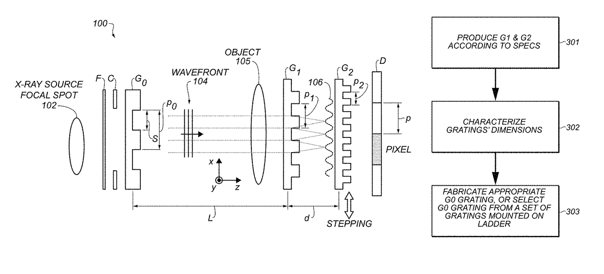
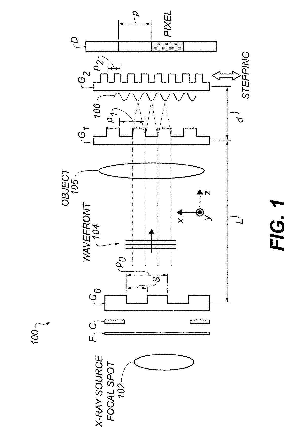
[0026]With reference to FIG. 1, the source grating G0 provides an array of individually coherent slit sources, which constructively contribute to image formation when the condition p0 / L=p2 / d is satisfied. In one embodiment, distance L is selected to be about 1.5 m and distance d about 42 mm. The source grating G0 and absorption grating G2 pitches, p0 and p2, respectively, are about 75 μm and 2 μm, respectively. Given that p0>>p2, and the distance L is more than 30 times larger than d, the system 100 performance is not sensitive to precise positioning of G0, and therefore, a rough alignment of grating bars is suitable for use along vertical axis y. In contrast, the relative alignment of G1 and G2 can have a significant impact on the performance of the PCI system. The gratings G0, G1, G2, are disposed in planes substantially parallel to each other and, as described herein, may be purposely rotated, or tilted, about the z axis while remaining parallel.

[0027]The geometrical properties o...


PUM

PropertyMeasurementUnit
tilt anglesaaaaaaaaaa
distanceaaaaaaaaaa

Abstract

A method for assembling a phase contrast x-ray imaging system includes fabricating a phase grating and an absorption grating according to a preselected pitch of the gratings. The actual obtained pitches are measured and a source grating is then fabricated according to a desired design point of the imaging system.

Description

CROSS REFERENCE TO RELATED APPLICATIONS[0001]This application claims priority to U.S. patent application Ser. No. 61 / 939,925, filed Feb. 14, 2014, in the name of Baturin et al., and entitled “METHOD AND APPARATUS FOR FABRICATION AND TUNING OF GRATING-BASED DIFFERENTIAL PHASE CONTRAST IMAGING SYSTEM.”[0002]This application is related in certain respects to U.S. patent application Ser. No. 14 / 143,254, filed Dec. 30, 2013, in the name of Baturin et al., and entitled LARGE FOV PHASE CONTRAST IMAGING BASED ON DETUNED CONFIGURATION INCLUDING ACQUISITION AND RECONSTRUCTION TECHNIQUES; U.S. patent application Ser. No. 13 / 729,443, filed Dec. 28, 2012, in the name of Baturin et al., and entitled SPECTRAL GRATING-BASED DIFFERENTIAL PHASE CONTRAST SYSTEM FOR MEDICAL RADIOGRAPHIC IMAGING; and U.S. patent application Ser. No. 13 / 724,096, filed Dec. 21, 2012, in the name of Baturin et al., and entitled GRATING-BASED DIFFERENTIAL PHASE CONTRAST IMAGING SYSTEM WITH ADJUSTABLE CAPTURE TECHNIQUE FOR M...

Claims


Application Information

Patent Timeline
Patent Type & Authority Patents(United States)
IPC IPC(8): G01N23/04A61B6/00
CPCA61B6/4035A61B6/4291A61B6/484A61B6/587
Inventor BATURIN, PAVLOSHAFER, MARK E.
Owner CARESTREAM HEALTH INC
Why Eureka
Try Eureka