Phase grating used to take X-ray phase contrast image, imaging system using the phase grating, and X-ray computer tomography system

a phase contrast and imaging system technology, applied in imaging devices, instruments, nuclear engineering, etc., can solve the problem of larger phase grating siz

Inactive Publication Date: 2013-01-08
CANON KK
View PDF5 Cites 40 Cited by
  • Summary
  • Abstract
  • Description
  • Claims
  • Application Information

AI Technical Summary

Benefits of technology

[0030]The present invention can realize a phase grating capable of acquiring, in photographing of an X-ray phase contrast image by use of X-ray with two wavelengths, an X-ray phase contrast image by the phase grating in the same size as when a single wavelength is used.

Problems solved by technology

However, Japanese Patent Application Laid-Open No. 2007-203074 of the conventional example has a problem that the size of the phase grating is larger than that when X-ray with a single wavelength is used.

Method used


Image

  • Phase grating used to take X-ray phase contrast image, imaging system using the phase grating, and X-ray computer tomography system
  • Phase grating used to take X-ray phase contrast image, imaging system using the phase grating, and X-ray computer tomography system
  • Phase grating used to take X-ray phase contrast image, imaging system using the phase grating, and X-ray computer tomography system

Examples


example 1

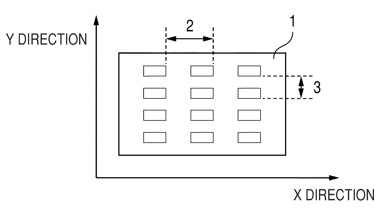
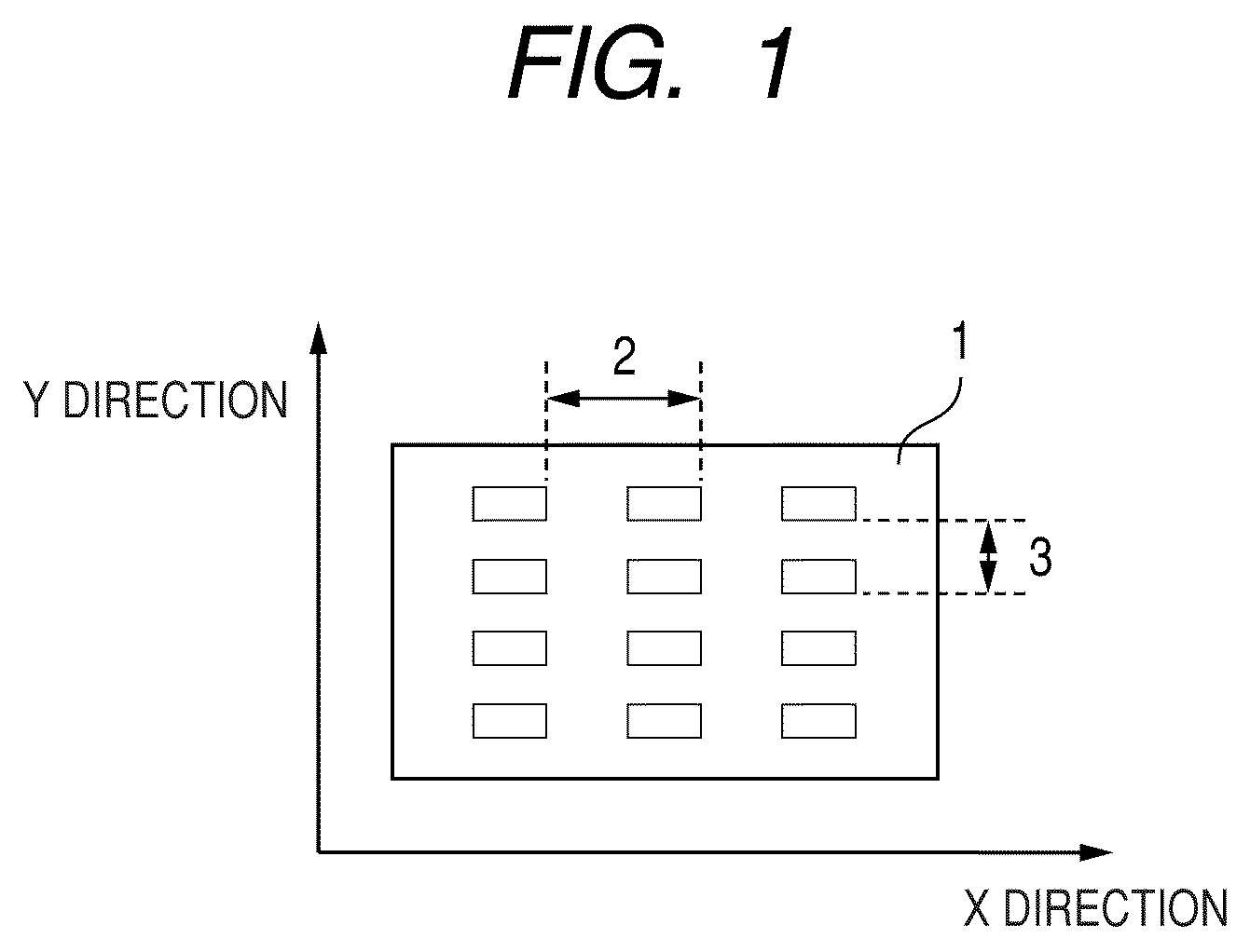
[0091]In Example 1, an example of configuration in which the phase grating 1 that has formed the periodic structures orthogonal to each other is used to take an X-ray phase contrast image by radiation light will be described.

[0092]In the present Example, resist coating is applied to a both-side polishing 200 μm thickness silicon wafer surface with 4-inch diameter, and then a resist pattern is created in an area of 60 mm square based on a photolithographic method.

[0093]The pitches of the resist pattern are different in the X and Y directions, and the resist pattern has a mesh structure in which the pattern in the X direction and the pattern in the Y direction are orthogonal.

[0094]More specifically, in the X direction, the resist pattern width has width 4 μm and aperture 4 μm. In the Y direction, the resist pattern has the line width 1.64 μm and space 1.64 μm.

[0095]Deep reactive ion etching (hereinafter, “Deep-RIE”) is performed to remove Si until the depth is 22.6 μm at the resist ap...

example 2

[0115]In Example 2, an example of configuration of using the phase grating 1 that has formed the periodic structures 10 orthogonal to each other to take an X-ray phase contrast image by a minute white X-ray source 6 will be described.

[0116]The phase grating 1 is created in the same method as Example 1. The resist pattern width in the X direction has the width 4 μm and the space 4 μm, and the resist pattern width in the Y direction has the width 1.64 μm and the space 1.64 μm. The size of the X-ray source is 5 μm, and the target is Mo.

[0117]The phase grating 1 is set at a location 1000 mm away from the X-ray source 6.

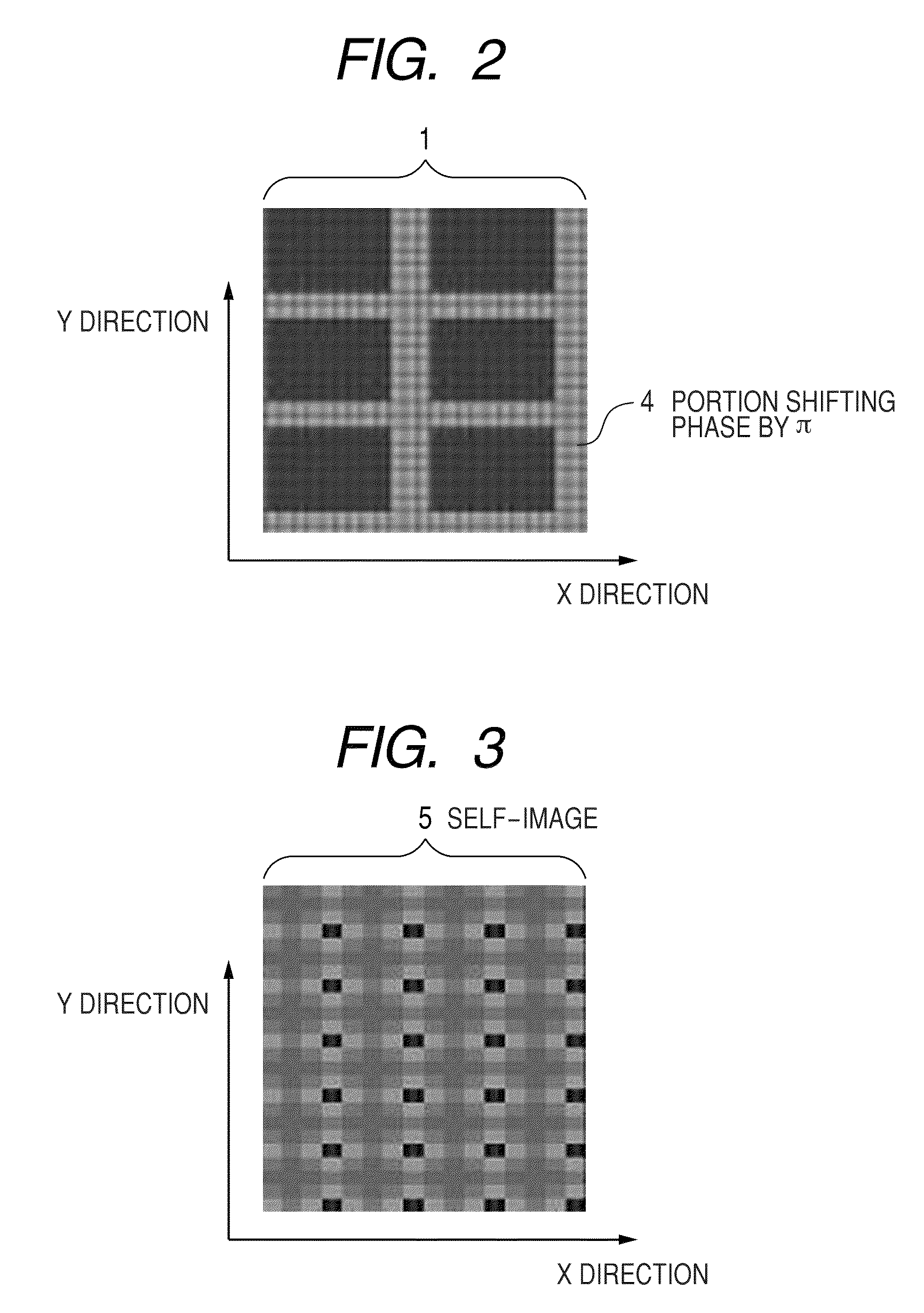
[0118]When the X-ray is directed to the phase grating 1, the self-image formed by the periodic structures 10 in the X and Y directions is formed at a location 128 mm away from the phase grating 1 in the opposite direction from the X-ray source as seen from the phase grating 1.

[0119]The absorption grating 8 created in the same way as in Example 1 is set at a location where...


PUM


Abstract

To provide a phase grating capable of acquiring, in photographing of an X-ray phase contrast image by use of X-ray with two wavelengths, an X-ray phase contrast image by a phase grating in the same size as when a single wavelength is used, provided is a phase grating used when an X-ray is directed to take an X-ray phase contrast image, the phase grating including a periodic structure for generating a phase difference between an X-ray transmitted through the structure and an X-ray not transmitted through the structure. The periodic structure has different periods in a plurality of directions in a same surface.

Description

BACKGROUND OF THE INVENTION[0001]1. Field of the Invention[0002]The present invention relates to a phase grating used to take an X-ray phase contrast image, an imaging system using the phase grating, and an X-ray computer tomography system.[0003]2. Description of the Related Art[0004]Conventionally, an X-ray fluoroscopic technique for using a difference between absorption capacities of X-ray to obtain a contrast image has been studied.[0005]However, the lighter the element is, the smaller is the absorption capacity of the X-ray. Therefore, there is a problem that enough contrast cannot be expected for soft biological tissues and soft materials.[0006]Thus, in recent years, an imaging method for generating contrast based on a phase shift of X-ray is studied.[0007]An example of an imaging method of X-ray phase contrast image (X-ray phase imaging method) using the phase contrast includes an imaging method using a Talbot interferometry.[0008]An outline of the imaging method of the Talbot...

Claims


Application Information

Patent Timeline
Patent Type & Authority Patents(United States)
IPC IPC(8): H05G1/60
CPCG21K1/06G21K2207/005
Inventor NAKAMURA, TAKASHIIMADA, AYA
Owner CANON KK
Why Eureka
Try Eureka