Absolute position miniature grating encoder readhead using fiber optic receiver channels

a fiber optic receiver and encoder technology, applied in the direction of optical conversion of sensor output, instruments, measurement devices, etc., can solve the problems of inability to convert suffer limitations in converting high frequency detector signals, and achieve high accuracy, high speed configuration, and low cost

Active Publication Date: 2006-05-30
MITUTOYO CORP
View PDF6 Cites 40 Cited by
  • Summary
  • Abstract
  • Description
  • Claims
  • Application Information

AI Technical Summary

Benefits of technology

[0021]Hence, the invention overcomes the disadvantages of prior art optical displacement sensing devices and provides new application possibilities with an absolute position, ultracompact, highly accurate, economical and high speed configuration.

Problems solved by technology

In addition to the fact that the previously disclosed '283 patent is directed only to a relative rather than absolute position system, the electronic readhead receivers (photodetectors) such as disclosed in the '283 patent suffer limitations in converting the high frequency detector signals associated with high speed scale motion and transmitting those signals over long cables without significant signal loss or interference.
In addition, electronic photodetectors and the associated circuit connections contribute to readheads that are too large for many potential encoder applications, particularly where multiple readhead portions are being used in a single readhead.
In addition to the fact that the previously discussed '071 patent is directed only to a relative rather than absolute position system, the optical fiber tip receptors such as those disclosed in the '071 patent have insufficient spatial resolution for fine phase signal discrimination if they have a large diameter, and gather too little light to provide a good signal if they have a small diameter.
Thus, their accuracy is limited.

Method used


Image

  • Absolute position miniature grating encoder readhead using fiber optic receiver channels
  • Absolute position miniature grating encoder readhead using fiber optic receiver channels
  • Absolute position miniature grating encoder readhead using fiber optic receiver channels

Examples


Embodiment Construction

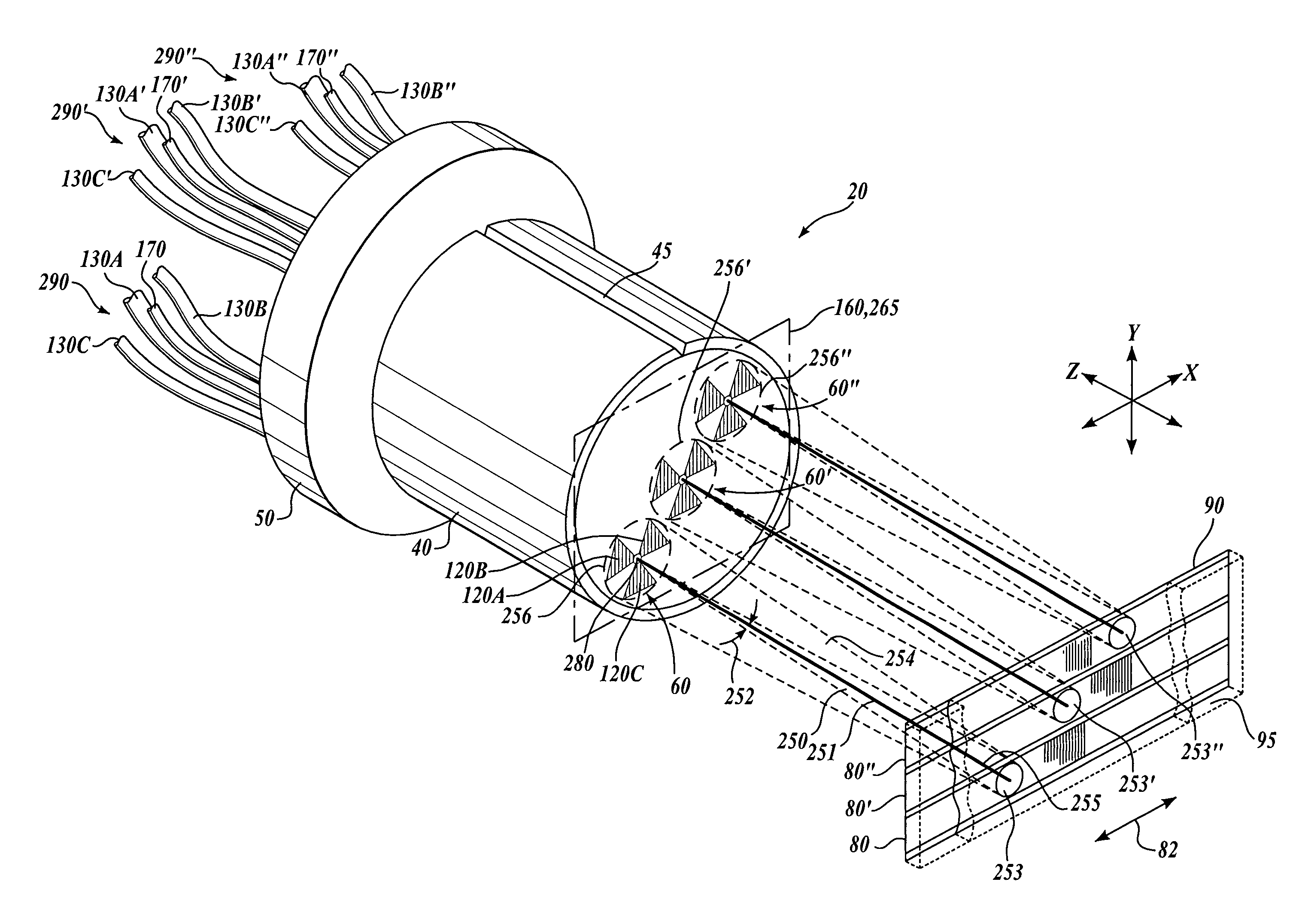
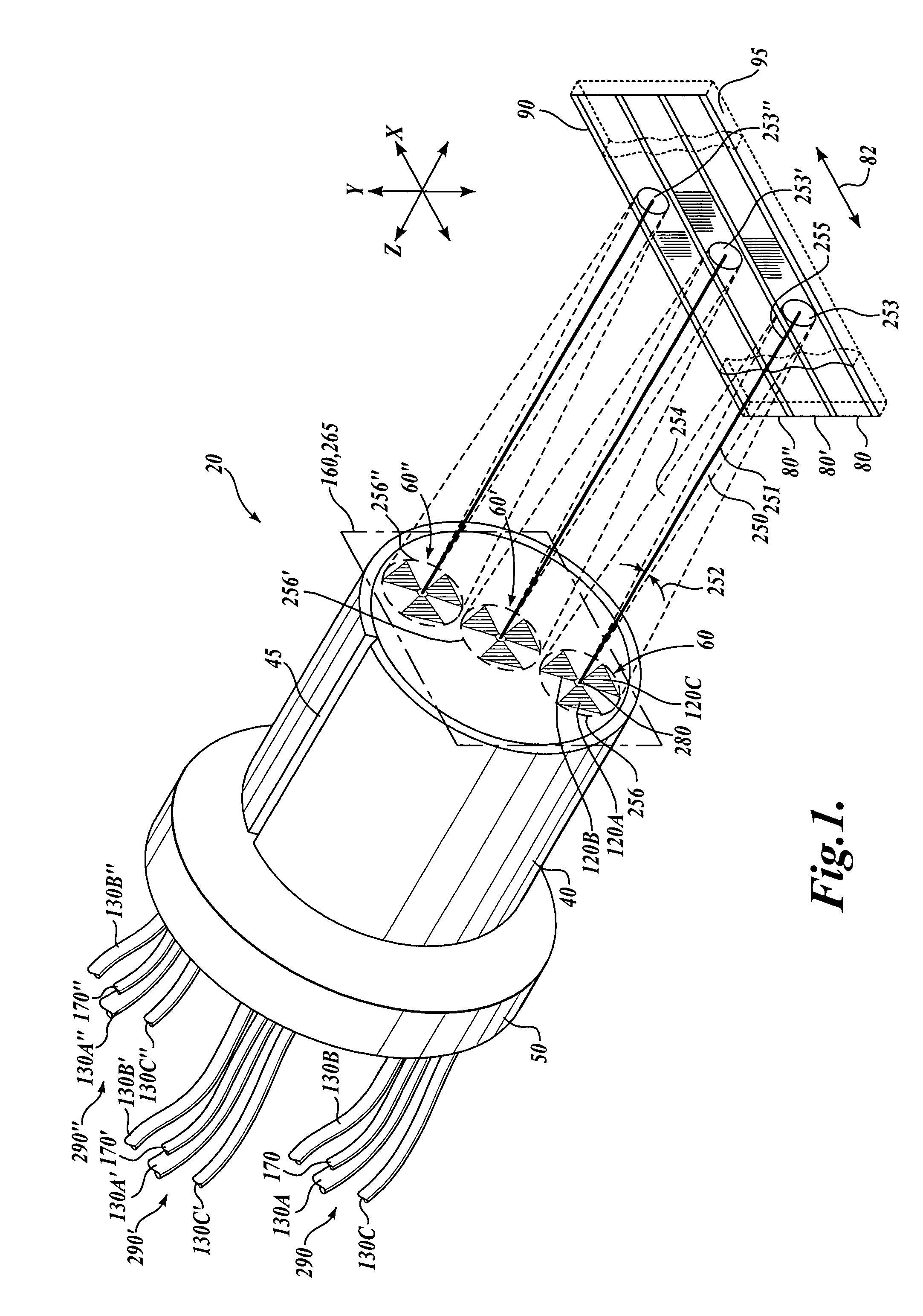
[0033]FIG. 1 shows a first generic embodiment of an absolute position fiber optic readhead arrangement 20 according to this invention. As shown in FIG. 1, the absolute position fiber optic readhead arrangement 20 includes a ferrule 40 which has an alignment groove 45 and an alignment collar 50, and which encases three readhead portions 60, 60′, and 60″. The readhead portions 60, 60′, and 60″ may be formed in accordance with the teachings of U.S. patent application Ser. No. 10 / 298,312, entitled “High Accuracy Miniature Grating Encoder Readhead Using Fiber Optic Receiver Channels,” filed Nov. 15, 2002, which is commonly assigned and hereby incorporated by reference in its entirety. As will be described in more detail below, each of the readhead portions 60, 60′, and 60″ corresponds to a scale track 80, 80′, and 80″, respectively, which are included on a scale 90, which is formed on a substrate 95. In one embodiment, as part of the absolute position system the three scale tracks 80, 80...


PUM


Abstract

An absolute position fiber optic encoder readhead having multiple readhead portions for sensing the displacement of respective scale grating tracks of a scale is disclosed. The detector channels of the readhead portions are fiber optic detector channels having respective phase grating masks. The fiber optic encoder readhead portions are configured to detect the displacement of a self-image of a respective scale grating track of the scale. In various exemplary embodiments, the fiber optic readhead portions are constructed according to various design relationships that provide a relatively high signal-to-noise ratio. Accordingly, high levels of displacement signal interpolation may be achieved, allowing submicrometer displacement measurements. The fiber optic encoder readhead portions may be assembled in a particularly accurate and economical manner and may be provided in a package with dimensions on the order of 1–2 millimeters, resulting in a very small overall absolute readhead dimension that is dependent on the number of readhead portions that are incorporated. Optical fiber receiver channels carrying binary optical signals derived from a scale code track may be provided in the readhead, to provide an extended absolute measurement range.

Description

FIELD OF THE INVENTION[0001]This invention relates generally to displacement sensing optical encoders, and more particularly to an absolute position optical encoder utilizing optical fibers as receiver elements to provide an ultracompact high accuracy absolute position system.BACKGROUND OF THE INVENTION[0002]Various movement or position encoders for sensing linear, rotary or angular movement are currently available. These encoders are generally based on either optical systems, magnetic scales, inductive transducers, or capacitive transducers. Certain of these encoders are designed for making relative, and not absolute, measurements. In such relative position encoders, measurements are typically made by sensing the relative change in position of the scales with respect to a reference position, which requires a continuous sensing of the change in the scale pattern so that repetitions of the pattern can be counted. The relative measurements require that a new reference or zero position...

Claims


Application Information

Patent Timeline
Patent Type & Authority Patents(United States)
IPC IPC(8): G01B9/02G01D5/30G01D5/347
CPCG01D5/34723
Inventor TOBIASON, JOSEPH D.ATHERTON, KIM W.
Owner MITUTOYO CORP
Why Eureka
Try Eureka