Reference signal generating configuration for an interferometric miniature grating encoder readhead using fiber optic receiver channels

a miniature grating encoder and readhead technology, applied in the field of reference signal generation configuration of miniature fiber optic encoders, to achieve the effect of high speed operation, small size and high accuracy

Inactive Publication Date: 2009-05-28
MITUTOYO CORP
View PDF13 Cites 10 Cited by
  • Summary
  • Abstract
  • Description
  • Claims
  • Application Information

AI Technical Summary

Benefits of technology

[0010]Importantly, a fiber optic reference signal generating configuration according to this invention offers desirable features similar to those of known miniature fiber optic grating encoders that provide incremental measurement (e.g., those disclosed in the '696 patent). For example, importantly, a fiber optic reference signal generating configuration according to this invention can be used at operating gaps similar or identical to the interferometric type fiber optic encoders disclosed in the '696 patent. In addition it offers similar extremely small size, high accuracy, electrical noise immunity, and very high speed operation. A miniature fiber optic reference signal generating configuration according to this invention is thus readily and economically combinable with desirable high-accuracy miniature fiber optic incremental measurement encoders.
[0011]Hence, the invention overcomes the disadvantages of prior art optical displacement sensing devices and provides new application possibilities with an ultra-compact, highly accurate, economical and high speed configuration.

Problems solved by technology

However, a reference signal generating configuration that is easily and economically combinable with miniature fiber optic grating encoders such as those included in the above references, and that provides similar desirable features, is not known.

Method used


Image

  • Reference signal generating configuration for an interferometric miniature grating encoder readhead using fiber optic receiver channels
  • Reference signal generating configuration for an interferometric miniature grating encoder readhead using fiber optic receiver channels
  • Reference signal generating configuration for an interferometric miniature grating encoder readhead using fiber optic receiver channels

Examples


first embodiment

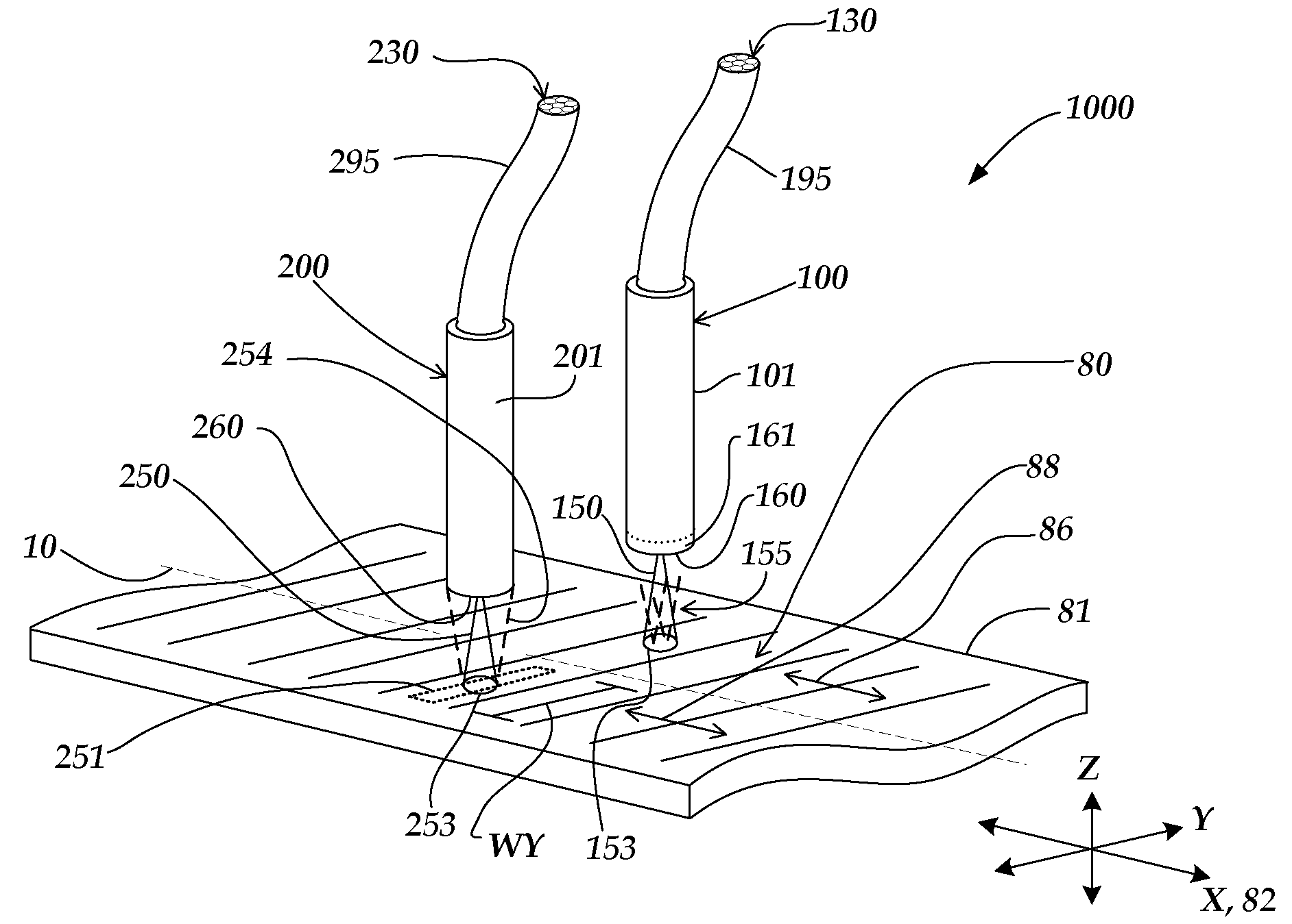
[0033]FIG. 1 is an isometric view of a miniature fiber optic readhead and scale arrangement 1000 that includes a reference signal generating configuration according to this invention. As shown in FIG. 1, the miniature fiber optic readhead and scale arrangement 1000 includes a scale member 81 that includes a scale grating 80, an incremental readhead 100, and a reference mark readhead 200. It will be appreciated the readheads 100 and 200 will generally be mounted rigidly relative to one another, or formed as a single unit, so that their displacements are synchronized.

[0034]An orthogonal XYZ coordinate system may be defined such that the y-axis is parallel to the bars of the scale grating 80, the z-axis is normal to the surface of the scale grating 80, and the x-axis is orthogonal to the y-z plane. A measuring axis 82 is parallel to the x-axis. In operation, the scale member 81 displaces along the measuring axis 82 such that the readhead 100 is displaced along an incremental measuring ...

second embodiment

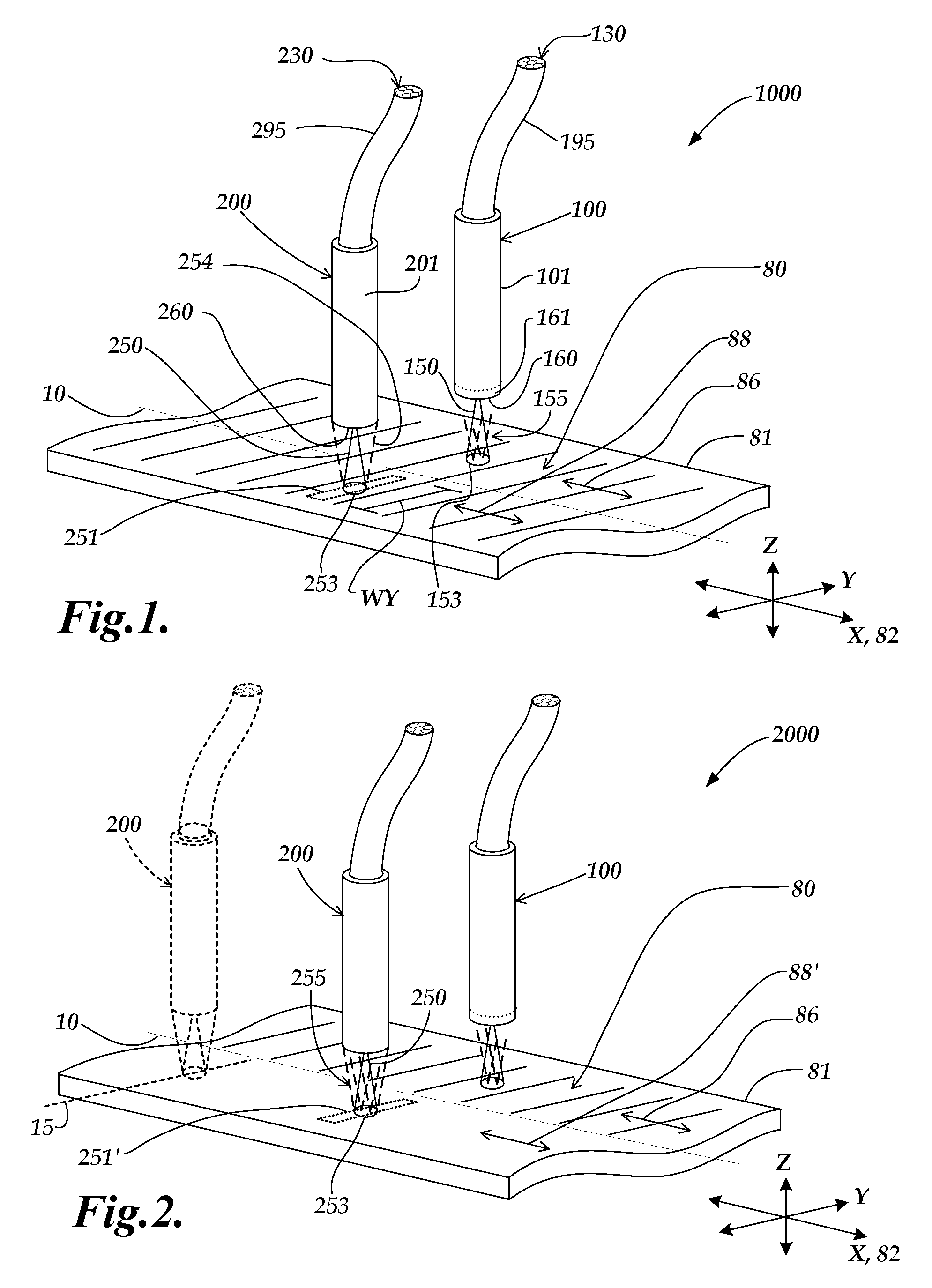
[0039]FIG. 2 is an isometric view of a miniature fiber optic readhead and scale arrangement 2000 that includes a reference signal generating configuration according to this invention. The operation of the miniature fiber optic readhead and scale arrangement 2000 is in some respects similar to that of miniature fiber optic readhead and scale arrangement 1000 of FIG. 1, and similarly numbered components may be similar or identical in form and operation, except as otherwise indicated below. As shown in FIG. 2, the miniature fiber optic readhead and scale arrangement 2000 includes a scale member 81 that includes a scale grating 80, an incremental readhead 100, and a reference mark readhead 200. A primary difference between the miniature fiber optic readhead and scale arrangement 2000 and miniature fiber optic readhead and scale arrangement 1000 is that the structure of reference scale track 88′ is different than that of reference scale track 88. In particular, at least that portion of t...

third embodiment

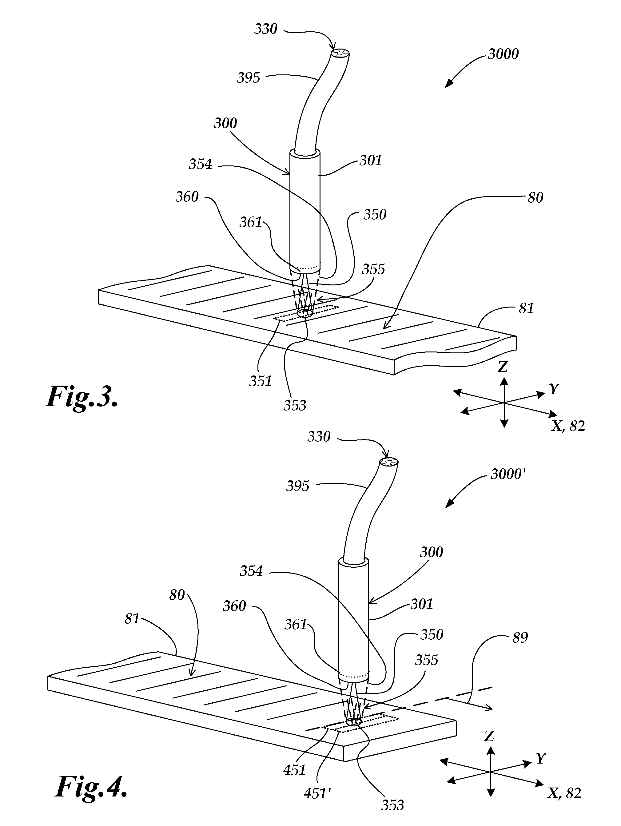
[0043]FIG. 3 is an isometric view of a miniature fiber optic readhead and scale arrangement 3000 that includes a reference signal generating configuration according to this invention. The operation of the miniature fiber optic readhead and scale arrangement 3000 is in some respects similar to that of miniature fiber optic readhead and scale arrangement 1000 of FIG. 1, and similarly numbered components may be similar or identical in form and operation, except as otherwise indicated below. As shown in FIG. 3, the miniature fiber optic readhead and scale arrangement 3000 includes a scale member 81 that has a single scale track that includes a scale grating 80 and a reference mark zone 351, and an integrated incremental and reference mark readhead 300, also referred to simply as an integrated readhead 300. The scale grating 80 may be a phase grating configured to suppress zero-order reflection. The reference mark zone 351 may include at least one mirror-like reference mark portion, as p...


PUM


Abstract

A reference mark configuration for an interferometric miniature grating encoder readhead using fiber optic receiver channels is provided. The readhead includes “primary” fibers that provide reference mark primary signals processed to generate a reference signal with accuracy of approximately 0.2 microns. The readhead may include “secondary” fibers used to generate reference mark secondary signals processed to generate a reference signal with accuracy of approximately 20 nanometers. Spatial filter masks configured for the secondary fiber optic receiver channels provide two spatially periodic secondary signals arising from interference fringes outside of the receiving area of the primary fiber optic receiver channels. The secondary signals are out of phase with one another and their spatial frequency is higher than that of the primary signals. A signal crossing of the reference mark secondary signals is identified that is spatially adjacent to a signal crossing of the reference mark primary reference signals.

Description

CROSS-REFERENCE TO RELATED APPLICATION[0001]This application is a continuation-in-part of patent application Ser. No. 11 / 782,608, filed Mar. 24, 2007, the disclosure of which is hereby expressly incorporated by reference herein.FIELD OF THE INVENTION[0002]This invention relates generally to displacement sensing optical encoders, and more particularly to providing a reference signal for a miniature fiber optic encoder utilizing optical fibers as receiver elements.BACKGROUND OF THE INVENTION[0003]Various miniature fiber optic grating encoders that use fiber optic receiver channels are known, including those disclosed in U.S. Pat. Nos. 6,906,315; 7,053,362; and 7,126,696, (hereinafter “the '315, '362, and '696 patents”) each of which is hereby incorporated herein by reference in its entirety. Such miniature encoders offer a desirable combination of features, which may include extremely small size, very high accuracy, electrical noise immunity, and very high speed operation.[0004]Many m...

Claims


Application Information

Patent Timeline
Patent Type & Authority Applications(United States)
IPC IPC(8): G01B11/14
CPCG01D5/268G01D5/366G01D5/34746G01D5/34723
Inventor ZWILLING, AVRONTOBIASON, JOSEPH DANIELHARSILA, SCOTTMASRELIEZ, KARL GUSTAV
Owner MITUTOYO CORP
Why Eureka
Try Eureka