Interferometric miniature grating encoder readhead using fiber optic receiver channels

a fiber optic receiver and encoder technology, applied in the field of displacement sensing optical encoders, can solve the problems of optical fiber tip receptors, optical readhead receivers (photodetectors), and suffer limitations in converting high frequency detector signals, and achieve high accuracy, high speed configuration, and economic

Active Publication Date: 2006-10-24
MITUTOYO CORP
View PDF9 Cites 58 Cited by
  • Summary
  • Abstract
  • Description
  • Claims
  • Application Information

AI Technical Summary

Benefits of technology

[0007]A high-resolution interferometric fiber optic encoder readhead for sensing the displacement of a scale grating is disclosed. Such an interferometric-type fiber optic encoder has certain advantages over previously known encoders. For example, compared to known crude fiber optic encoders and conventional self-imaging encoders, this interferometric-type encoder can operate with a relatively smaller scale pitch, in order to conveniently provide finer measurement resolution. Furthermore, such an interferometric-type encoder can operate reliably over a much larger range of operating gaps relative to the scale, allowing simpler installation and more reliable operation. The readhead includes a light source for transmitting light to the scale grating and detector channels for receiving light from the scale grating. In accordance with one aspect of the invention, the detector channels of the encoder readhead are fiber optic detector channels. Electronic readhead receivers (photodetectors) such as disclosed in the '283 patent suffer limitations in converting the high frequency detector signals associated with high speed scale motion and transmitting those signals over long cables without significant signal loss or interference. In addition, electronic photodetectors and the associated circuit connections contribute to readheads that are too large for many potential encoder applications. It will be appreciated that the fiber optic detector channels of the present invention overcome these limitations.
[0021]Hence, the invention overcomes the disadvantages of prior art optical displacement sensing devices and provides new application possibilities with an ultra-compact, highly accurate, economical and high speed configuration.

Problems solved by technology

Electronic readhead receivers (photodetectors) such as disclosed in the '283 patent suffer limitations in converting the high frequency detector signals associated with high speed scale motion and transmitting those signals over long cables without significant signal loss or interference.
Optical fiber tip receptors such as those disclosed in the '071 patent have insufficient spatial resolution for fine phase signal discrimination if they have a large diameter, and gather too little light to provide a good signal if they have a small diameter.
Thus, their accuracy is limited.

Method used


Image

  • Interferometric miniature grating encoder readhead using fiber optic receiver channels
  • Interferometric miniature grating encoder readhead using fiber optic receiver channels
  • Interferometric miniature grating encoder readhead using fiber optic receiver channels

Examples


Embodiment Construction

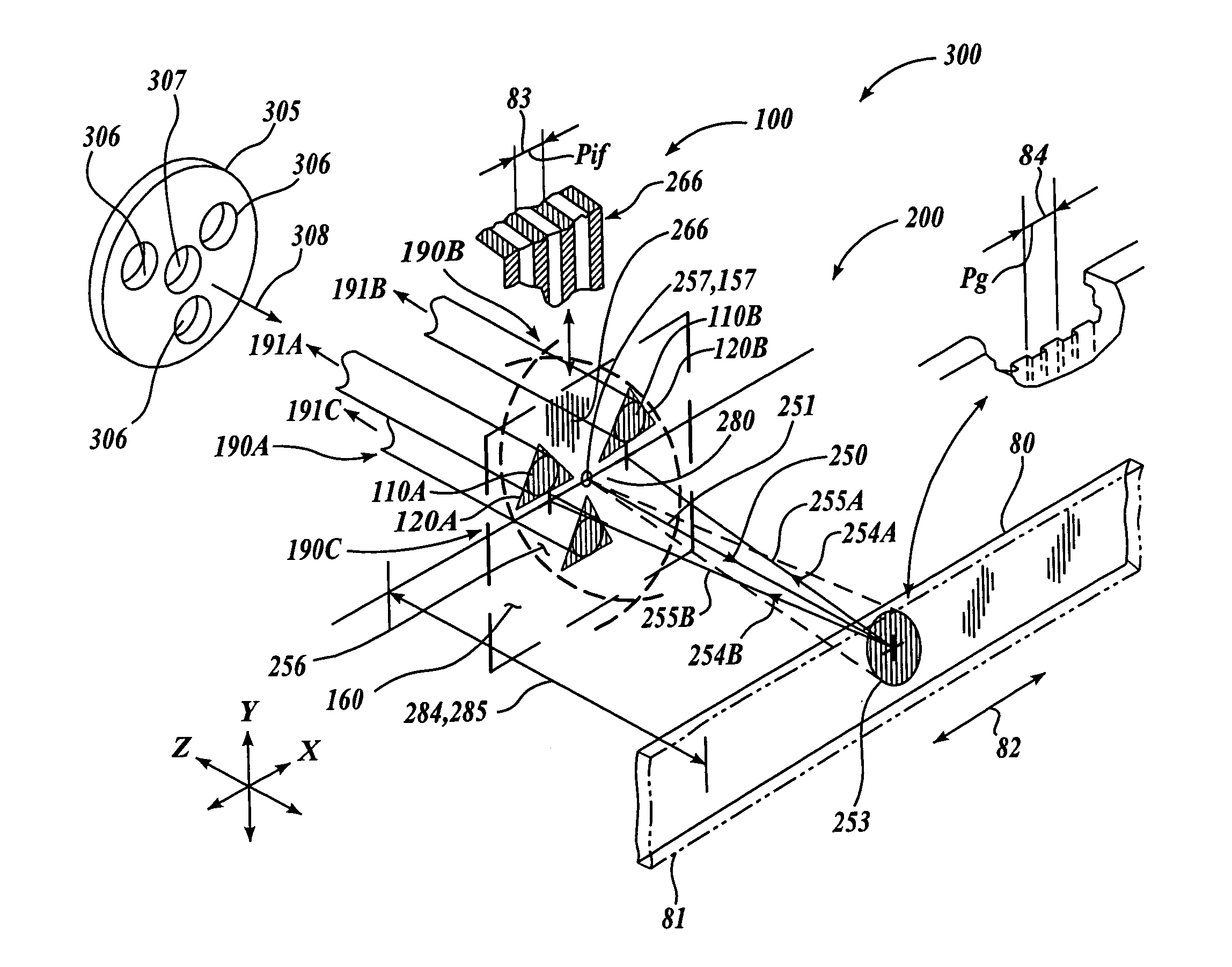
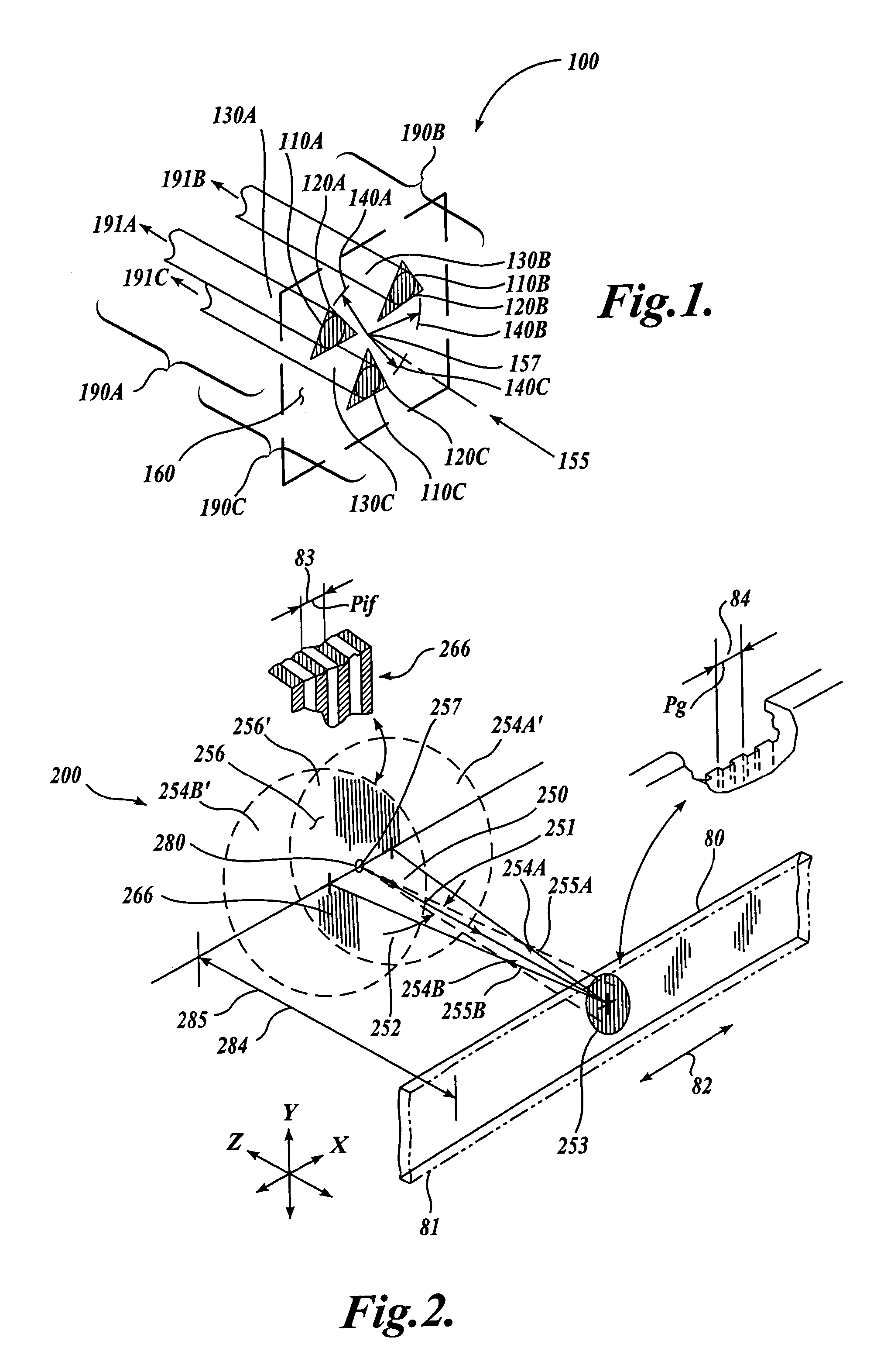
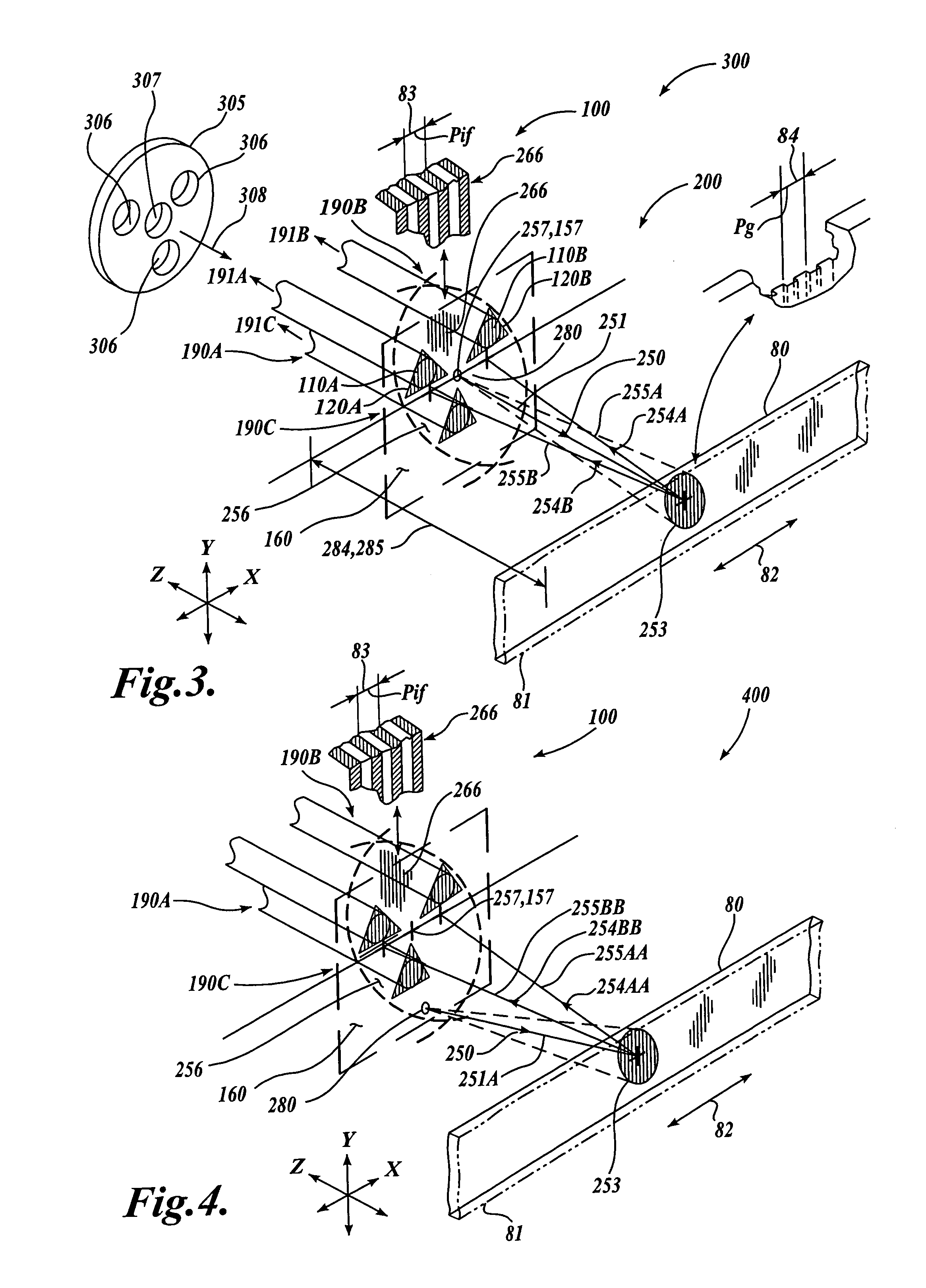
[0045]FIG. 1 shows a first generic embodiment of a fiber-optic receiver channel arrangement 100 according to this invention. As shown in FIG. 1, the fiber-optic receiver channel arrangement 100 includes three fiber-optic receiver channels 190A, 190B and 190C. The fiber-optic receiver channel 190A includes a receiver channel aperture 110A, a phase mask 120A, and a receiver optical fiber 130A. Similarly, the fiber-optic receiver channel 190B includes a receiver channel aperture 110B, a phase mask 120B, and a receiver optical fiber 130. Similarly, the fiber-optic receiver channel 190C includes a receiver channel aperture 110C, a phase mask 120C, and a receiver optical fiber 130C.

[0046]For each fiber-optic receiver channel 190, the phase mask 120 includes a grating that completely covers the receiver channel aperture 110, acting as a spatial filter for incoming illumination. The receiver optical fiber 130 is aligned with the receiver channel aperture 110 such that nominally all illumina...


PUM


Abstract

An interferometric fiber optic encoder readhead for sensing the displacement of a scale grating is disclosed. The detector channels of the readhead are fiber optic detector channels having respective phase grating masks. The fiber optic encoder readhead is configured to detect the displacement of interference fringes arising from the scale grating. In various exemplary embodiments, the fiber optic readhead is constructed and operably positioned according to various design relationships that insure a compact mounting and a relatively ideal sinusoidal signal as a function of displacement. Accordingly, high levels of displacement signal interpolation may be achieved, allowing sub-micrometer displacement measurements. The fiber optic encoder readhead may be assembled in a particularly accurate and economical manner and may be provided in a package with dimensions on the order of 1–2 millimeters.

Description

FIELD OF THE INVENTION[0001]This invention relates generally to displacement sensing optical encoders, and more particularly to an optical encoder utilizing optical fibers as receiver elements to provide an ultra-compact high accuracy system.BACKGROUND OF THE INVENTION[0002]Various movement or position encoders for sensing linear, rotary or angular movement are currently available. These encoders are generally based on either optical systems, magnetic scales, inductive transducers, or capacitive transducers.[0003]For optical encoders, a number of systems have been developed. One recent system that is compact and utilizes fewer parts than most previous systems is disclosed in U.S. Pat. No. 5,909,283, to Eselun. The system described in the '283 patent has a grating scale and readhead including a point source (laser diode in readhead), a Ronchi grating or holographic element, and a photodetector array. As described, the point source results in interference fringes having a spacing equa...

Claims


Application Information

Patent Timeline
Patent Type & Authority Patents(United States)
IPC IPC(8): G01B9/02G01D5/38G01B11/00G01D5/347
CPCG01D5/34723G01D5/38
Inventor TOBIASON, JOSEPH D.
Owner MITUTOYO CORP
Why Eureka
Try Eureka