Device for extracorporeal blood treatment

a technology for extracorporeal blood and blood vessels, which is applied in the direction of medical devices, suction devices, other medical devices, etc., can solve the problems of unfavorable effects, inability to temporally resolve, and often not being able to distinguish with certainty, so as to improve the quality of measuring signals

Active Publication Date: 2017-07-11
B BRAUN AVITUM
View PDF36 Cites 3 Cited by
  • Summary
  • Abstract
  • Description
  • Claims
  • Application Information

AI Technical Summary

Benefits of technology

[0013]Therefore, it is an object of the invention to provide a generic device for extracorporeal blood treatment, which makes it possible to achieve a better quality of the measuring signal for determining the concentration and / or determining the dialysis dosage.
[0015]Apart from the previous use for the (quasi) static determination of a measure for the concentration of uremic toxins, the quantification of transients, i.e. temporal courses of concentration changes, becomes more and more predominant. Concentration transients deliver information about dynamic patient and machine parameters wtube knowledge allows a physician to improve the quality of the therapy individually for each patient. The current positioning of the UV measuring equipment exhibiting a long fluid-carrying path and / or a high volume between the dialyzer and the measuring equipment, however, brings about some unfavorable effects. On the one hand, the draining dialysis liquid flows through a series of fluid-carrying elements on its way between the dialyzer and the UV measuring device, which due to their volume contribute to the fact that concentration changes are leveled out and cannot be temporally resolved any more. Convective mixing effects occur here which will change the transients to a large extent, right up to a complete dispersal of their information content. In the resultant measuring signal, it is frequently not possible to distinguish with certainty if there is a case of a temporarily occurring concentration peak of the waste product in question or a longer-lasting increase. The information about patient and therapy which are comprised in the transients, will get lost here. Typical elements in the dialysis liquid drain of a dialysis machine which bring about this effect are balancing equipments, e.g. balance chambers or air separators.
[0017]Whereas the degeneration of the transients due to convectively acting elements can be prevented by arranging the measuring equipment between the dialyzer and the respective elements, the avoidance of any diffusive degeneration of the transient signal requires further considerations:
[0027]This parabolic flow profile has the effect that any concentration changes which occur at a place z=0, can be measured with sufficient precision at a place z>0 only after a finite time t. This time t is longer than the time
[0063]The device, according to aspects of the invention, for extracorporeal blood treatment may include any apparatus which are suitable for dialysis, in particular artificial kidneys and dialysis machines. The invention offers the advantage of improving the measuring accuracy and sharpness of the measuring signal for determining the concentration of physiological waste products to be removed from the blood. Thus, the problems involved in an extracorporeal blood treatment which have been depicted above are solved and the identification and quantification of concentration changes are made possible with particularly accuracy.

Problems solved by technology

The current positioning of the UV measuring equipment exhibiting a long fluid-carrying path and / or a high volume between the dialyzer and the measuring equipment, however, brings about some unfavorable effects.
On the one hand, the draining dialysis liquid flows through a series of fluid-carrying elements on its way between the dialyzer and the UV measuring device, which due to their volume contribute to the fact that concentration changes are leveled out and cannot be temporally resolved any more.
In the resultant measuring signal, it is frequently not possible to distinguish with certainty if there is a case of a temporarily occurring concentration peak of the waste product in question or a longer-lasting increase.
On the other hand, there will be a significant temporal delay between the occurrence of a concentration or concentration change in the dialysis liquid of the dialysis liquid-side chamber of the dialyzer and its proof by means of the measuring device.
It may happen that several minutes lapse until the arrival of the signal at the measuring equipment.
Here again, there will be a loss of information.

Method used


Image

  • Device for extracorporeal blood treatment
  • Device for extracorporeal blood treatment
  • Device for extracorporeal blood treatment

Examples


Embodiment Construction

[0075]The Figures are purely illustratively and therefore not true to scale. Identical elements or elements having the same effect are provided with identical reference symbols, unless otherwise stated.

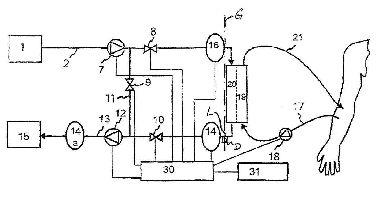
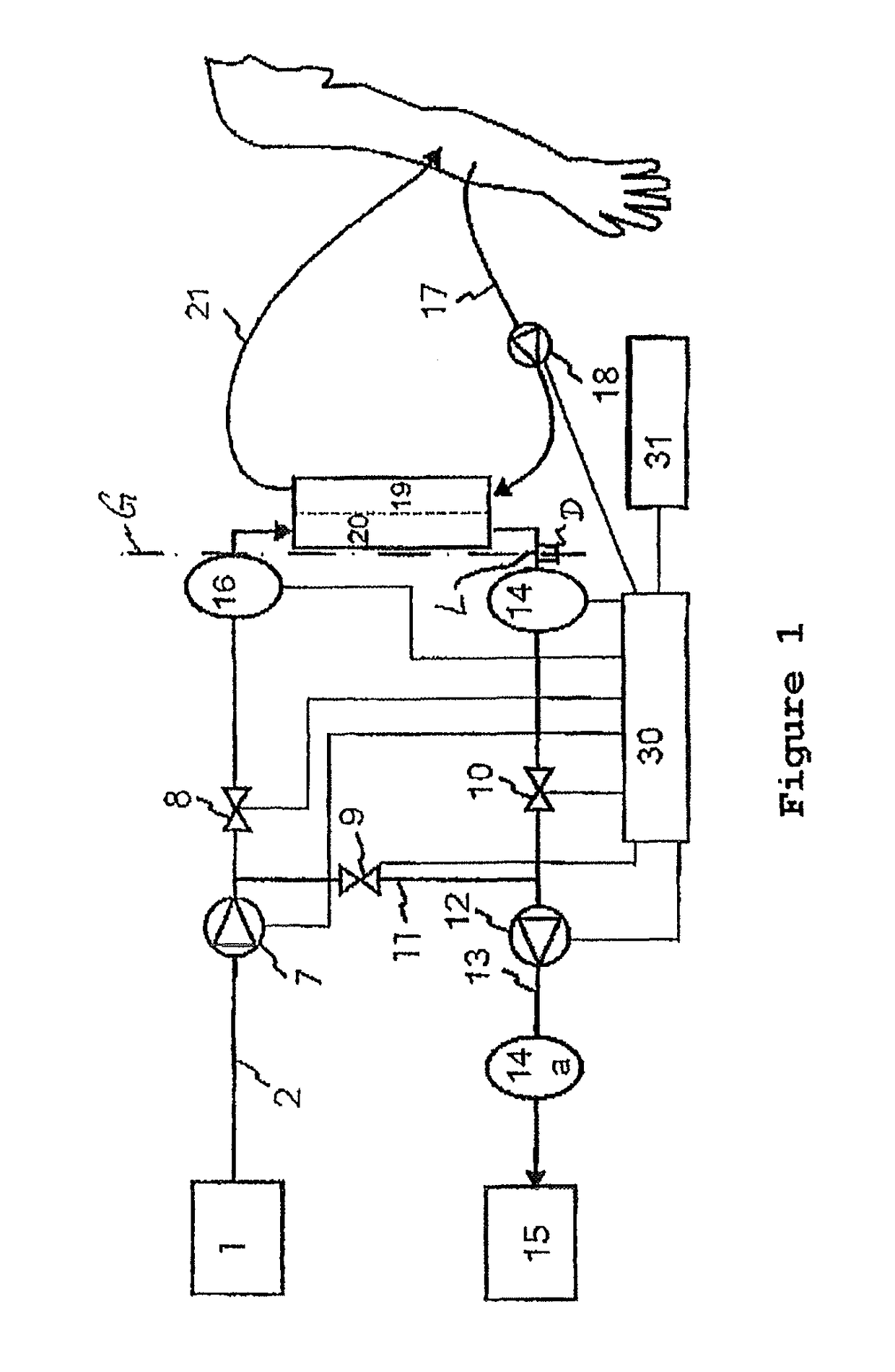
[0076]FIG. 1 shows a first embodiment of the dialysis liquid circuit according to aspects of the invention in a device for extracorporeal blood treatment (e.g. a dialysis machine). Here, the device is used for carrying out a hemodialysis without any substitution of liquid. Fresh dialysis liquid is supplied from a dialysis liquid source 1 and fed into the circuit via an inflow 2. To this end, a flow pump (FPE) 7 is provided upstream of a filter element (dialyzer). A first valve (VDE) 8 between the flow pump 7 and the filter element closes or opens an inlet of the filter element. A second valve (VDA) 10 downstream of the filter element opens or closes the dialysis liquid circuit with respect to an outlet of the filter element. In analogy to the inlet side, the outlet side of the filter ...


PUM


Abstract

A device for extracorporeal blood treatment is disclosed that includes a detection equipment for detecting uremic toxins in a used dialysis liquid by measuring the absorbance, the detection equipment being provided at such a position downstream the outflow of the dialysis liquid from a filter element that at least one of the following requirements is fulfilled: a) the filling volume of the fluid line and of the components starting from the outflow of the used dialysis liquid from the filter element to the detection equipment is less than or equal to 100 ml; and b) the length of the fluid line starting from the outflow of the used dialysis liquid from the filter element to the detection equipment is at most 250 cm.

Description

CROSS REFERENCE TO RELATED APPLICATIONS[0001]This application claims priority to German application DE 10 2013 104 501.4 filed May 2, 2013, the contents of such application being incorporated by reference herein.FIELD OF THE INVENTION[0002]The invention relates to a device for extracorporeal blood treatment.BACKGROUND OF THE INVENTION[0003]Patients suffering from a restricted or lacking renal function will have the waste products of the natural metabolism (including uremic toxins) removed by renal substitution methods or dialysis methods. Here, removing the substances from the blood, which is taken from the patient and conveyed in extracorporeal manner, is performed through the contact of the blood with a dialysis liquid; in this process, the blood and the dialysis liquid are not in direct contact, but contact each other via a semi-permeable membrane. The dialysis liquid is charged with various salts. The removal of the physiological waste products is carried out through diffusive a...

Claims


Application Information

Patent Timeline
Patent Type & Authority Patents(United States)
IPC IPC(8): B01D61/30B01D61/32A61M1/16
CPCA61M1/1609A61M1/1617B01D61/30B01D61/32A61M2202/0498A61M2205/3306A61M2205/3313
Inventor STROHHOEFER, CHRISTOFKRAUSE, SILVIERITTER, KAI-UWEMEIBAUM, JOERN
Owner B BRAUN AVITUM
Why Eureka
Try Eureka