
Rotary joint support structure spindle of machine tool, and electric motor

a technology of supporting structure and rotary joint, which is applied in the direction of metal-working machine components, maintenance and safety accessories, metal-working apparatus, etc., can solve the problems of large amount of coolant leaked into the chamber, difficult to drain newly leaked coolant, and concentrated coolant which leaks out of the rotary joint, so as to eliminate the need for detachable stopper parts and reliably drain the coolant from the rotary joint

Active Publication Date: 2017-07-11
FANUC LTD
View PDF14 Cites 0 Cited by
  • Summary
  • Abstract
  • Description
  • Claims
  • Application Information

AI Technical Summary

Benefits of technology

[0010]The present invention was made in consideration of such a situation and has as its object the provision of a rotary joint support structure which enables easy cleaning of a chamber of a rotary joint and a drain hole and cutaway part and the provision of a spindle of a machine tool and electric motor which are provided with such a rotary joint support structure.
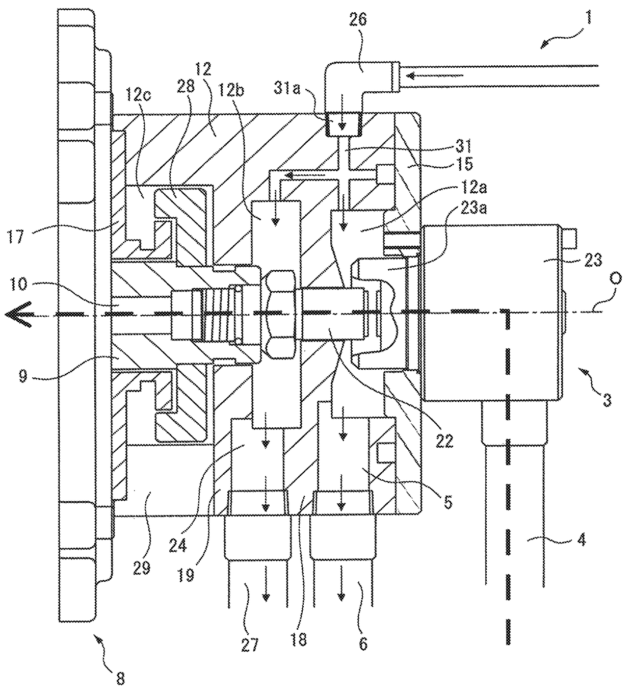
[0019]In the first, seventh, and eighth aspects of the invention, by feeding fluid to the first cleaning passage and the second cleaning passage, the fluid makes the coolant which had leaked out into the rotary joint holding part and hollow shaft holding part flow out to a drain hole and cutaway part. In other words, the first cleaning passage and the second cleaning passage can be used to easily clean a holding part, drain hole, and cutaway part, so coolant or contaminant can be kept from causing the holding part, drain hole, and cutaway part to be closed. Further, since there is no need to disassemble the rotary joint support structure, a holding part, drain hole, and cutaway part can be easily cleaned. Furthermore, in the seventh and eighth aspects of the invention, the spindle and electric motor can be improved in reliability.
[0020]In the second aspect of the invention, the flinger is spun so that the coolant and contaminant are flung off, so a holding part, drain hole, and cutaway part can be cleaned more efficiently.
[0022]In the fourth aspect of the invention, it is possible to eliminate the need for detaching the stopper part when feeding cleaning fluid to at least one of the first cleaning passage and the second cleaning passage.
[0023]In the fifth aspect of the invention, it is possible to feed cleaning fluid by a desired pressure to at least one of the first cleaning passage and the second cleaning passage, so coolant or contaminant can be reliably drained from the rotary joint.

Problems solved by technology

In this regard, when a center-thru coolant feed operation is frequently performed or when the quality of the coolant which is used is low, the coolant which leaks out from the rotary joint becomes concentrated and acts as a contaminant.
Such a contaminant sometimes obstructs the operation of the rotary joint and causes a large amount of coolant to leak into the chamber.
Further, if a contaminant clogs a drain hole or cutaway part, it becomes difficult to drain the newly leaked coolant.
For this reason, if a contaminant clogs a drain hole or cutaway part, the inside of the spindle or electric motor will sometimes be invaded by the coolant, poor lubrication of the spindle bearing will be caused, or poor insulation will be caused at the electric motor.
However, at the time of cleaning, the rotary joint and the surrounding parts have to be disassembled, so the cleaning work is complicated.

Method used


Image

  • Rotary joint support structure spindle of machine tool, and electric motor
  • Rotary joint support structure spindle of machine tool, and electric motor
  • Rotary joint support structure spindle of machine tool, and electric motor

Examples


Embodiment Construction

[0035]Below, embodiments of the present invention will be explained with reference to the attached drawings. In the following drawings, similar members are assigned similar reference notations. To facilitate understanding, these figures are suitably change in scale.

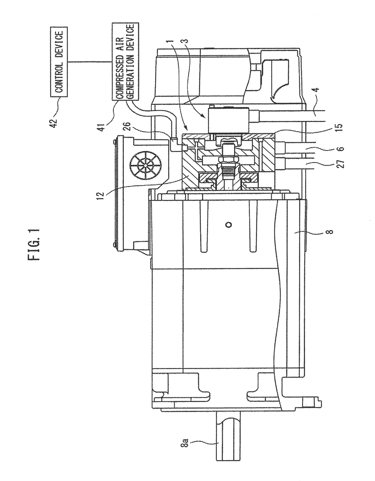
[0036]FIG. 1 is a side cross-sectional view of a motor which is provided with a rotary joint support structure according to the present invention. As shown in FIG. 1, a rotary joint support structure 1 is arranged coaxially with an output shaft 8a at an end part of a motor 8 at an opposite side from a hollow output shaft 8a. The rotary joint support structure 1 includes a rotary joint 3. At the circumferential surface of its housing 12, an air purge pipe 26 is connected. Further, as explained later, the motor is made one which is used for driving a spindle of a machine tool.

[0037]As shown in FIG. 1, the air purge pipe 26 is connected to a cleaning fluid source, for example, a compressed air generation device 41. The compr...


PUM


Abstract

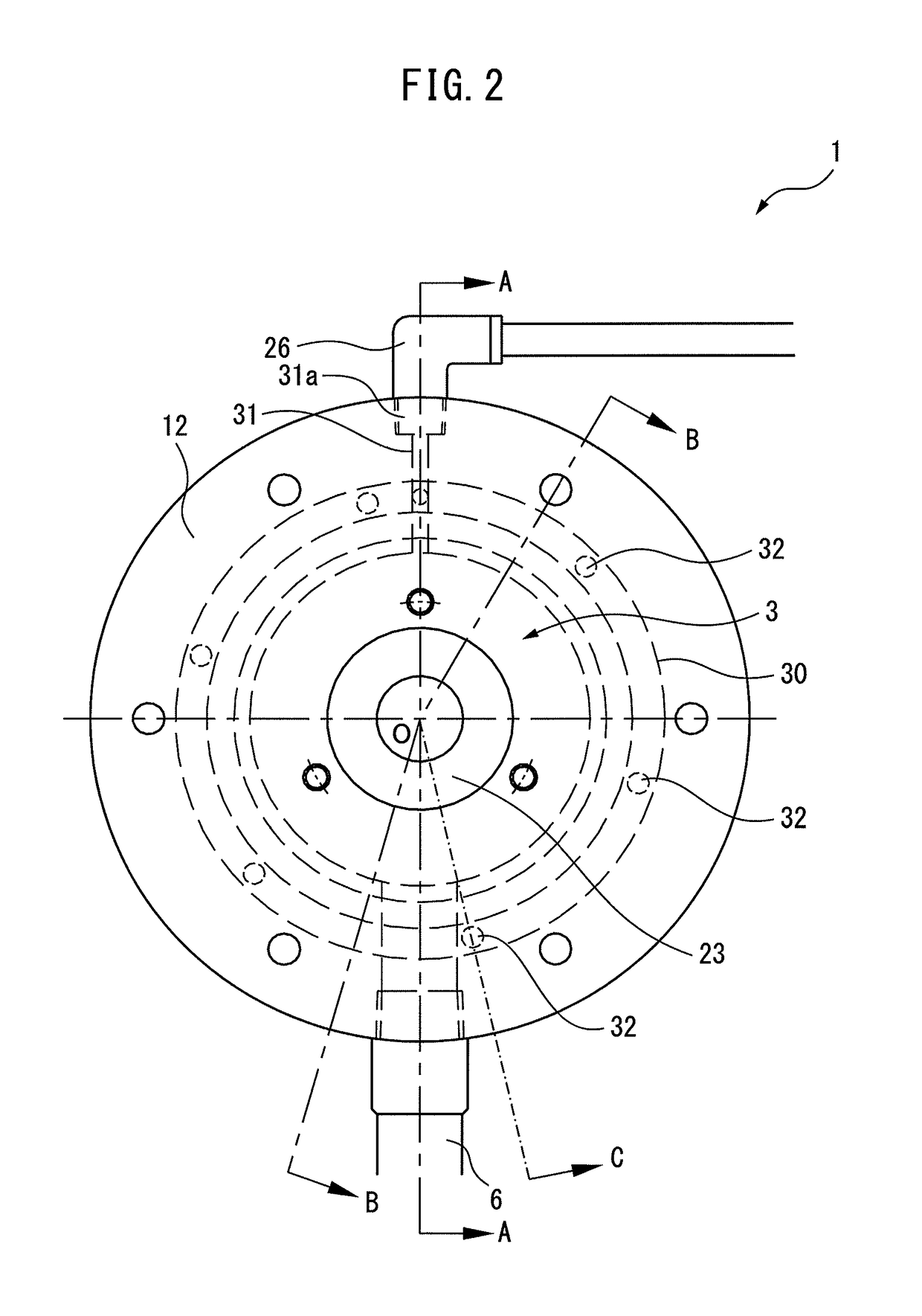
A rotary joint support structure includes a rotary joint holding part which covers contact parts between a rotating side member and a stationary side member, at least one drain hole which extends from the outside to the rotary joint holding part, a first cleaning passage which communicates with the rotary joint holding part, a hollow shaft holding part which covers the hollow shaft and hollow shaft surrounding part, at least one cutaway part which is formed so as to communicate the outside with the hollow shaft holding part, and a second cleaning passage which is formed inside the housing corresponding to the at least one cutaway part.

Description

BACKGROUND OF THE INVENTION[0001]1. Field of the Invention[0002]The present invention relates to a rotary joint support structure which performs a center-thru coolant feed operation and a spindle of a machine tool and electric motor which are provided with such a rotary joint support structure.[0003]2. Description of the Related Art[0004]In a machine tool, to improve the machining precision of a workpiece and extend the tool life, a coolant is run through a bore formed in a spindle etc. up to the machining point so as to cool the machining point in a “center-thru coolant” feed operation. In the spindle etc. which is carried at a machine tool in which a center-thru coolant feed operation is performed, to increase the speed of the spindle and improve the reliability, the general practice has been to use a detachable outside support type rotary joint to feed high pressure coolant.[0005]A detachable outside support type rotary joint includes a rotating part which rotates together with t...

Claims


Application Information

Patent Timeline
Patent Type & Authority Patents(United States)
IPC IPC(8): F16L39/04B23Q11/10
CPCB23Q11/103F16L39/04
Inventor NAKAZAWA, YASUYUKI
Owner FANUC LTD
Learn More