Paper conveying apparatus and method

a conveying apparatus and paper technology, applied in the direction of printing press parts, thin material processing, printing, etc., can solve the problems of paper contact with the droplet ejection surface of the head, the recording quality degrades, and the recording surface of the paper changes, so as to prevent collision and prevent collision

Active Publication Date: 2017-07-11
FUJIFILM CORP
View PDF10 Cites 0 Cited by
  • Summary
  • Abstract
  • Description
  • Claims
  • Application Information

AI Technical Summary

Benefits of technology

[0011]The present invention is made considering such circumstances, and the object of the invention is to provide a paper conveying apparatus and a paper conveying method which detect degradation of a drive transmission belt while detecting paper abnormality and prevent collision between a recording medium and an apparatus arranged in a conveyance path beforehand.
[0027]According to the present invention, it is possible to detect the degradation of a drive transmission belt while detecting paper abnormality and prevent collision between a recording medium and an apparatus arranged in a conveyance path beforehand.

Problems solved by technology

In an inkjet recording apparatus, when a paper to be conveyed floats from the conveyance surface of a conveying cylinder or conveyance belt which holds the paper, there are problems that: the distance from the droplet ejection surface of an inkjet head to the recording surface of the paper changes and the recording quality degrades; and the paper contacts with the droplet ejection surface of the head and the droplet ejection surface is damaged.
However, when a drive transmission belt degrades, there are problems that: it takes time until the paper conveyance stops after the paper float is caused, due to the occurrence of slip between the drive transmission belt and a pulley; and a floated paper collides with the inkjet head.

Method used


Image

  • Paper conveying apparatus and method
  • Paper conveying apparatus and method
  • Paper conveying apparatus and method

Examples


first embodiment

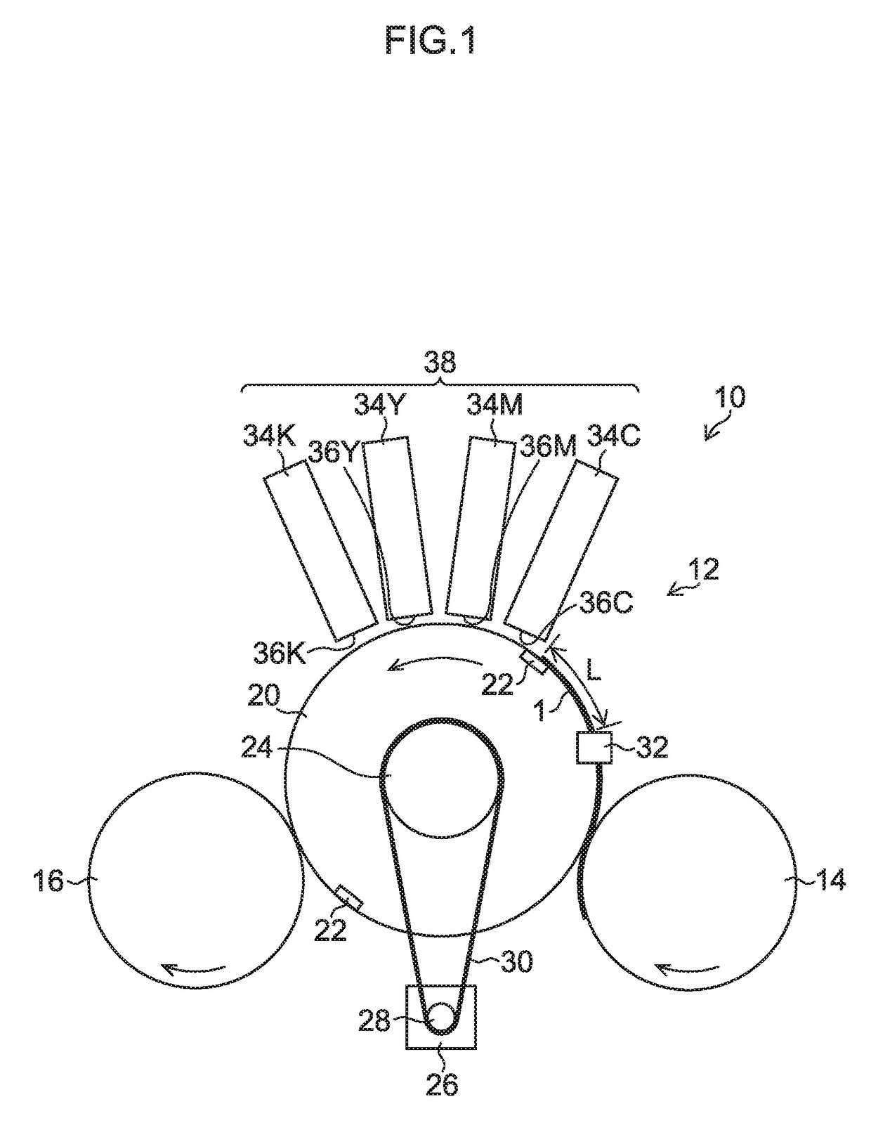
Outline of Inkjet Recording Apparatus: First Embodiment

[0037]An inkjet recording apparatus according to the present embodiment determines degradation of a drive transmission belt and informs the degradation to a user. As illustrated in FIG. 1, the inkjet recording apparatus 10 is a line printer of a single-pass system to form an image on a recording surface of a paper 1, and includes a conveying portion 12 and a recording portion 38.

[0038]The conveying portion 12 (one example of a paper conveying apparatus) includes an upstream transfer cylinder 14, a downstream transfer cylinder 16 and a jetting cylinder 20.

[0039]The paper 1 conveyed by the upstream transfer cylinder 14 is transferred to the jetting cylinder 20 (one example of a conveying apparatus and one example of a rotating body) and conveyed by the jetting cylinder 20. The recording portion 38 (one example of an image forming device) deposits ink in the paper 1 conveyed by the jetting cylinder 20 and forms an image on the reco...

second embodiment

System Configuration of Conveying Portion: Second Embodiment

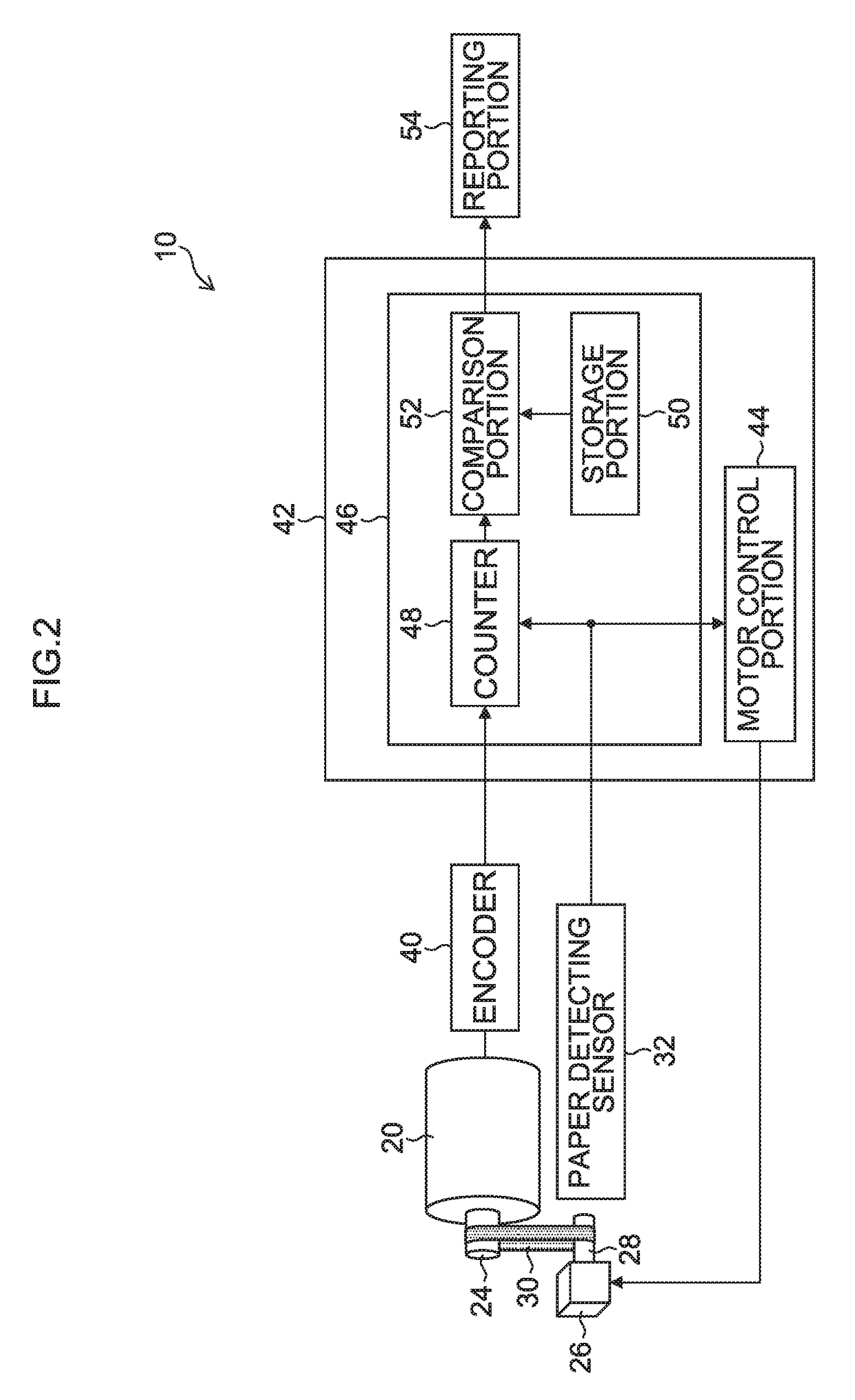
[0075]Next, a conveying portion according to the second embodiment is described using FIG. 5. Here, the same reference numerals are assigned to portions common with FIG. 2, and detailed explanation thereof is omitted.

[0076]As illustrated in FIG. 5, the conveying portion 60 includes a self-diagnosis portion 62 and an inactive portion 64.

[0077]The self-diagnosis portion 62 (one example of a self-diagnosing device) operates the paper detecting sensor 32 in a pseudo or compulsive manner to perform self-diagnosis of the degradation of the belt 30. Here, if the self-diagnosis portion 62 is set to a self-diagnosis mode of the belt 30 by the user from an inputting device (not illustrated), an abnormality detection signal of the paper detecting sensor 32 is compulsorily generated. The motor control portion 44, the counter 48, the storage portion 50, the comparison portion 52 and the reporting portion 54 operate according to this sig...

third embodiment

Configuration of Inkjet Recording Apparatus: Third Embodiment

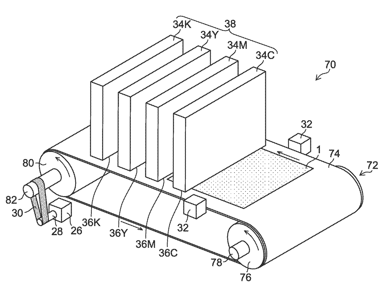
[0080]Next, an inkjet recording apparatus according to the third embodiment is described using FIG. 6. Here, the same reference numerals are assigned to portions common with FIG. 1 and detailed explanation thereof is omitted.

[0081]As illustrated in FIG. 6, the inkjet recording apparatus 70 is a single-pass line printer of a single-pass system to form an image on the recording surface of the paper 1, and includes a conveying portion 72 and the recording portion 38.

[0082]The conveying portion 72 is a conveying device of a belt conveyance system to suck and hold the paper 1 that is a recording medium on a conveyance belt 74 and convey the paper 1. The conveyance belt 74 is an endless belt having a width larger than the width of the conveyed paper 1, and is wound around an upstream roller 76 and a downstream roller 80.

[0083]The upstream roller 76 and the downstream roller 80 (one example of a rotating body) are supported to a ...


PUM


Abstract

A paper conveying apparatus includes: a driving device which rotates a driving rotating body by driving force; a conveying device which conveys a paper along a conveyance path according to rotation of a driven rotating body; an endless drive transmission belt which is stretched to the driving rotating body and the driven rotating body; a conveyance amount detecting device which detects a conveyance amount of the paper; an abnormality detecting device which detects abnormality of the paper; a stopping device which stops the driving device when the abnormality is detected; a calculating device which calculates the conveyance amount in time before conveyance stops after the abnormality is detected; a degradation detecting device which compares the calculated conveyance amount and a threshold and determines that the drive transmission belt is degraded if the calculated conveyance amount is larger than the threshold; and a reporting device which reports a determination result.

Description

CROSS-REFERENCE TO RELATED APPLICATIONS[0001]The present application claims priority under 35 U.S.C. §119 to Japanese Patent Application No. 2015-071080, filed on Mar. 31, 2015. The above application is hereby expressly incorporated by reference, in its entirety, into the present application.BACKGROUND OF THE INVENTION[0002]Field of the Invention[0003]The present invention relates to a paper conveying apparatus and a paper conveying method, and specifically relates to a paper conveyance technique that transmits the driving force of a driving device to a carrier by a drive transmission belt.[0004]Description of the Related Art[0005]An inkjet recording apparatus makes droplets of ink be deposited from an inkjet head to the recording surface of a paper which is conveyed through a predetermined conveyance path to record an image. This paper conveyance is performed by transmitting the driving force caused by a motor to a conveying cylinder which holds a paper in the peripheral surface or...

Claims


Application Information

Patent Timeline
Patent Type & Authority Patents(United States)
IPC IPC(8): B65H7/02B65H5/22B41F23/08B41J13/08B41J29/38B65H63/036B41J13/22B65H5/02B65H7/06
CPCB65H7/06B41F23/08B41J13/08B41J13/223B41J29/38B65H5/021B65H5/224B65H5/226B65H63/036B65H2403/20B65H2511/22B65H2511/30B65H2511/417B65H2513/512B65H2553/51B65H2601/12B65H2220/03B65H2220/01
Inventor SUMIYOSHI, YUTA
Owner FUJIFILM CORP
Why Eureka
Try Eureka