Variable volume sample capture device

a capture device and variable volume technology, applied in the field of variable volume sample capture devices, can solve problems such as false readings of captured samples, and achieve the effect of greater efficiency

Active Publication Date: 2017-07-11
LIQUID ANALYSIS SYST INC
View PDF60 Cites 2 Cited by
  • Summary
  • Abstract
  • Description
  • Claims
  • Application Information

AI Technical Summary

Benefits of technology

[0017]It is still another object of the variable volume capture device to allow for changing syringe and barrel diameters and lengths to accommodate larger or smaller ranges of samples. While the linear drive shaft can capture a variable amount of fluid with each sample, capture of small samples that have a volume of the plunger fluid path can be imprecise, whereby changing to a smaller syringe and barrel will provide greater efficiency. At the other extreme, if a large sample that exceeds the volume of a syringe barrel, a larger syringe and barrel can be utilized.

Problems solved by technology

If the syringe barrel is not flushed, cross contamination of test fluids can cause false readings of the captured samples.

Method used


Image

  • Variable volume sample capture device
  • Variable volume sample capture device
  • Variable volume sample capture device

Examples


Embodiment Construction

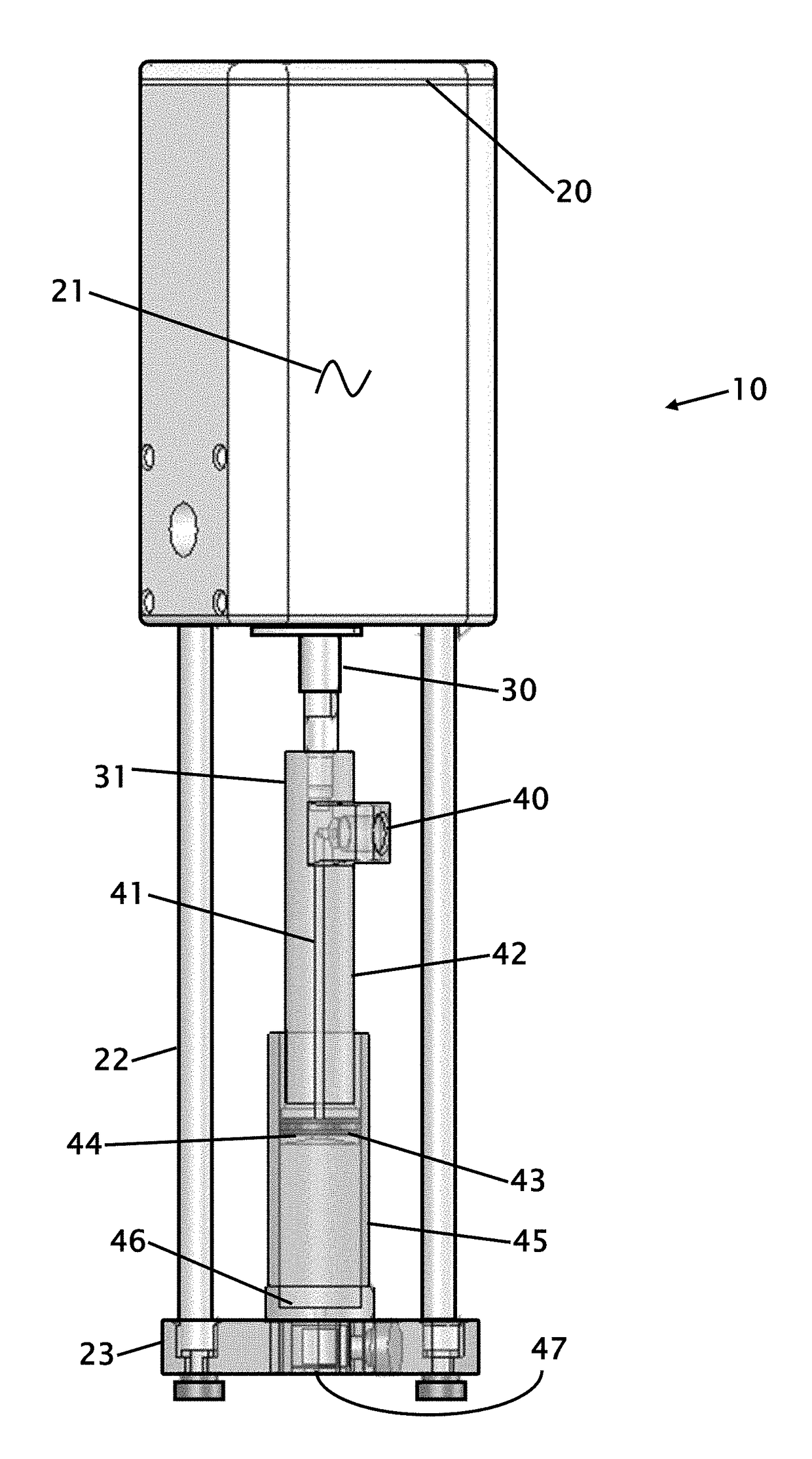
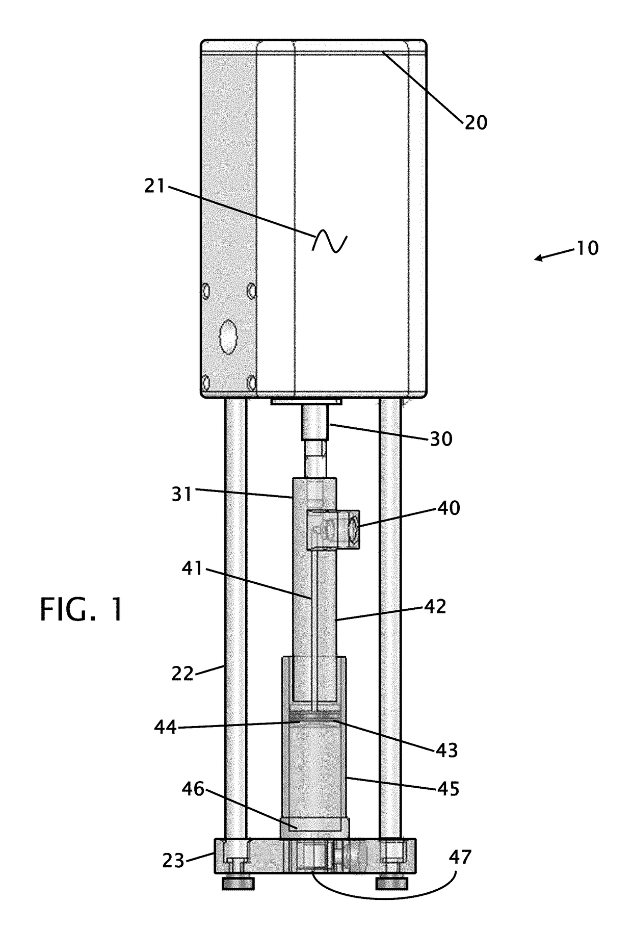
[0024]FIG. 1 shows the syringe and plunger assembly. This figure shows the motor housing 21 having a motor access plate 20 on top of top of the motor housing 21. The motor housing has a linear drive shaft 30 that moves the sample collecting device in a linear motion into the sample that is being collected. The structure has a syringe bracket frame 22 that connects to a syringe bracket base 23. The linear actuator can be pneumatic, hydraulic or electrically powered.

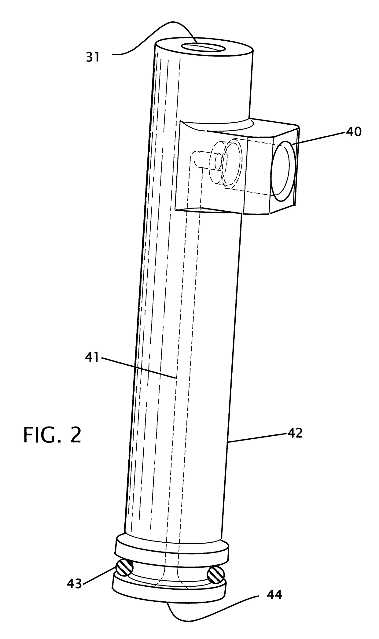
[0025]There is a threaded coupling 31 that connects the linear drive shaft 30 to the plunger 42. The plunger 42 has an upper fluid port 40 where captured fluid is expelled to a drain or dispensed for testing. Within the plunger 42 is a fluid path 41 for captured fluid to travel. The bottom of the plunger 42 is retained in the syringe barrel 45 and is sealed with a plunger seal 43 at the funnel entrance 44. The bottom of the syringe barrel 45 has a syringe nose piece 46 connecting the syringe cavity to the lower fluid port ...


PUM

PropertyMeasurementUnit
stroke lengthaaaaaaaaaa
volumeaaaaaaaaaa
transparentaaaaaaaaaa

Abstract

Improvements in a variable volume capture device are disclosed to capture a variable amount of sample. The variable amount is controlled by a linear actuator that produces a variable and adjustable stroke length that capture the programmed amount of fluid in the syringe barrel. Air or other supernatant fluid can be separated and expelled at this point. The captured fluid is then dispensed out of the syringe barrel for further testing and analysis. The capture device is then able to drain or flush the sample. Valves located on each side of the syringe barrel allow for sample collecting, dispensing and draining to ensure that the capture device is free to collect new samples. The variable volume capture device can have changeable syringe and barrel diameters and lengths to accommodate larger or smaller ranges of samples.

Description

CROSS REFERENCE TO RELATED APPLICATION[0001]Not ApplicableSTATEMENT REGARDING FEDERALLY SPONSORED RESEARCH OR DEVELOPMENT[0002]Not ApplicableTHE NAMES OF THE PARTIES TO A JOINT RESEARCH AGREEMENT[0003]Not ApplicableINCORPORATION-BY-REFERENCE OF MATERIAL SUBMITTED ON A COMPACT DISC[0004]Not ApplicableBACKGROUND OF THE INVENTION[0005]Field of the Invention[0006]This invention relates to improvements in a variable volume capture device. More particularly, the present variable volume capture device that allows for capture and delivery of a representative and exact volume of liquid for online (or at-line) chemical analysis. In particular, this is intended for use on the sampling and analysis of multiple sample sources.[0007]Description of Related Art Including Information Disclosed Under 37 CFR 1.97 and 1.98[0008]Many industries today use chemical processing in, for example, mining, food processing, refining, water treatment, recycling, and semiconductor manufacture, metal and plastic su...

Claims


Application Information

Patent Timeline
Patent Type & Authority Patents(United States)
IPC IPC(8): G01N1/14
CPCG01N1/14G01N2001/1427
Inventor BALISKY, TODD A
Owner LIQUID ANALYSIS SYST INC
Why Eureka
Try Eureka