Magnetic switch

a technology of magnetic switch and switch ball, which is applied in the direction of contact mechanism, mechanical actuation of burglar alarm, instruments, etc., can solve the problems of affecting the utility of the magnetic switch, the switch ball of the switch can hang up or become stuck in the simultaneous electrode contact position, and the switch ball cannot be moved freely

Active Publication Date: 2017-07-11
MAGNASPHERE
View PDF23 Cites 3 Cited by
  • Summary
  • Abstract
  • Description
  • Claims
  • Application Information

AI Technical Summary

Benefits of technology

The present invention provides magnetic switch assemblies that are designed to prevent sticking or hangup of the shiftable components. The switch assemblies have a housing with an elongated electrode and a conductive component that can shift between first and second switch positions. The first switch position is when the shiftable component is in simultaneous contact with both electrodes, and the second switch position is when the component is out of simultaneous contact. The switch includes a housing with an elongated section of reduced diameter and an enlarged section of greater diameter, so that the component can simultaneously contact both electrodes. In some embodiments, the switch may be used as a part of an alarm system or for monitoring the positions of the switches. The switch is shiftable between a position where the housing is adjacent to an actuating component to create the corresponding magnetic field operating on the shiftable component, and another position where the housing is remote from the actuating component and a different magnetic field condition is established. The shiftable component may be a magnet or a magnetic material, and the biasing element and actuating component may be metallic materials. The first electrode has an elongated section of reduced, substantially constant diameter, and the enlarged section may be of any desired shape such as frustoconical or circular.

Problems solved by technology

This type of switch is subject to unauthorized manipulation through use of an external magnet.
In the absence of sophisticated switch ball conditioning, the switch balls of these switches can hang up or become stuck in the simultaneous electrode contact positions thereof, owing to frictional forces encountered between the balls and electrodes.
This is a problem which can detract from the utility of the magnetic ball switches.

Method used


Image

  • Magnetic switch
  • Magnetic switch

Examples


Embodiment Construction

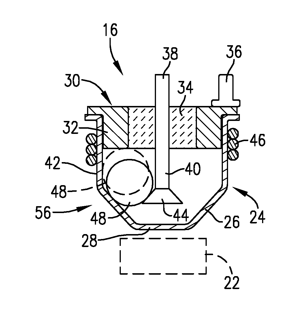
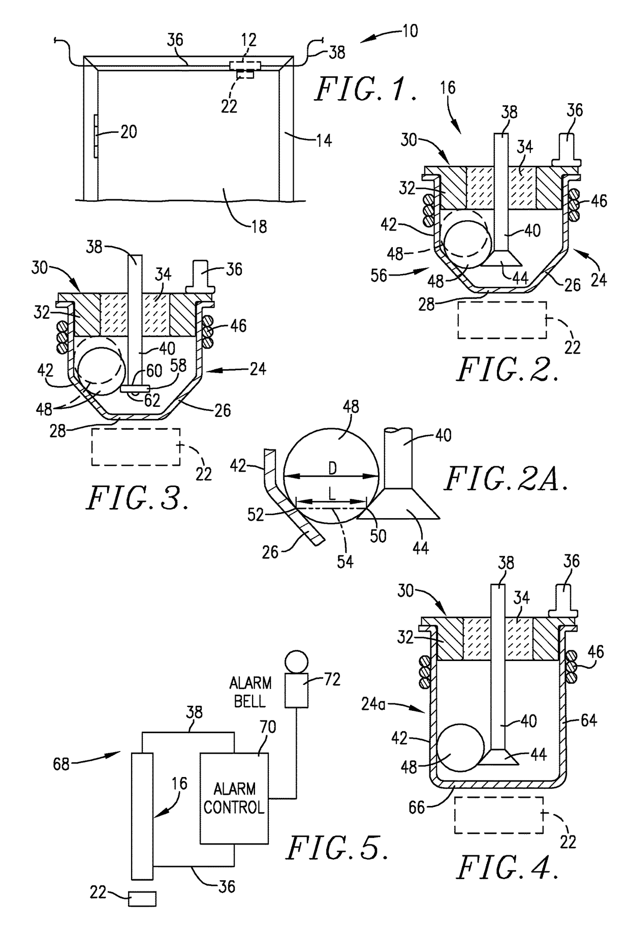
[0016]FIG. 1 illustrate a switch assembly 10 including a housing 12 adapted to be mounted within a stationary door frame 14 and having a magnetic switch 16 therein. In this illustration, the assembly 10 is designed to monitor the condition of door 18 within frame 14 via hinges 20. The switch 16 operates in conjunction with an actuating body 22 mounted on door 18, so that when the latter is closed, the body 22 is in direct adjacency with switch 16.

[0017]The switch 16 is illustrated in FIG. 2 and has a hollow metallic housing 24 presenting a circular in cross-section converging wall 26 terminating in a lowermost wall 28. A cover 30 is affixed to the upper end of housing 24 and includes an outer, annular, electrically conductive metallic segment 32 and an inner central segment 34 formed of non-conductive material, such as glass, ceramic, or synthetic resin. A pair of electrical leads 36 and 38 are respectively secured to segment 32 and a rod-like electrode extending through the central...


PUM


Abstract

An improved magnetic switch assembly (16) has a housing (24), a first electrode (40) positioned within the housing (24), a second electrode (42), and a magnetically movable component (48) located within the housing (24) and shiftable between a first position in simultaneous contact with electrodes (40, 42), and a second position out of such simultaneous contact. The electrode (40) has a radially enlarged contact section (44, 58) adjacent the free end thereof which prevents hangup or sticking of component (48) in the first position.

Description

BACKGROUND OF THE INVENTION[0001]Field of the Invention[0002]The present invention is broadly concerned with improved magnetic switch assemblies which overcome the tendency of some prior switches to hang up or stick owing to frictional forces encountered during switch operation. More particularly, the invention is concerned with such switch assemblies having a housing with an elongated electrode extending into the housing and having a free end. The electrode includes an enlarged diameter section adjacent the inner free end of the electrode to prevent switch malfunction.[0003]Description of the Prior Art[0004]Prior art alarm systems use magnetic switches attached to doors and / or windows for detecting unauthorized opening thereof. One common type of magnetic switch is a so-called reed switch. This type of switch is subject to unauthorized manipulation through use of an external magnet. That is, an intruder can use a strong magnet held in proximity to the reed switch to hold the switch...

Claims


Application Information

Patent Timeline
IPC IPC(8): H01H36/00
CPCH01H36/0073H01H36/00H01H36/0046G08B13/08H01H3/161H01H2003/165H01H2036/0086G08B29/046
Inventor HEDEEN, JOSEPH C.WOODS, RANDALLHEDEEN, LARRY
Owner MAGNASPHERE
Why Eureka
Try Eureka