Method and system for rendering a synthetic aperture radar image

a synthetic aperture radar and image technology, applied in the field of synthetic aperture radar image rendering, can solve the problems of not being able to discriminate objects having the same distance to the cylinder axis, combining the series of observations requires significant computational resources, etc., and achieves the effect of facilitating the training of interpretation of sar images

Active Publication Date: 2017-07-18
MAXAR INT SWEDEN AB
View PDF29 Cites 3 Cited by
  • Summary
  • Abstract
  • Description
  • Claims
  • Application Information

AI Technical Summary

Benefits of technology

[0017]One object of the present disclosure is to f

Problems solved by technology

Combining the series of observations requires significant computational resources, usually using Fourier transform techniques.
Accordingly, it is not pos

Method used


Image

  • Method and system for rendering a synthetic aperture radar image
  • Method and system for rendering a synthetic aperture radar image
  • Method and system for rendering a synthetic aperture radar image

Examples


Embodiment Construction

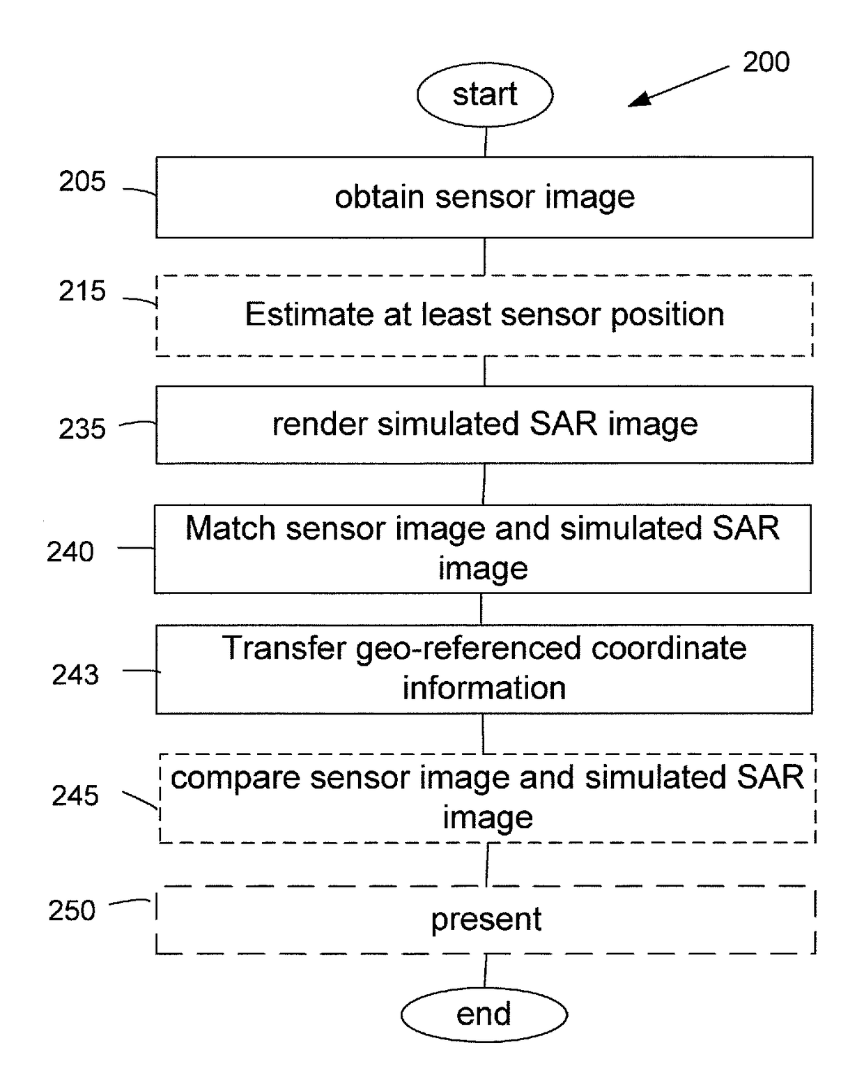
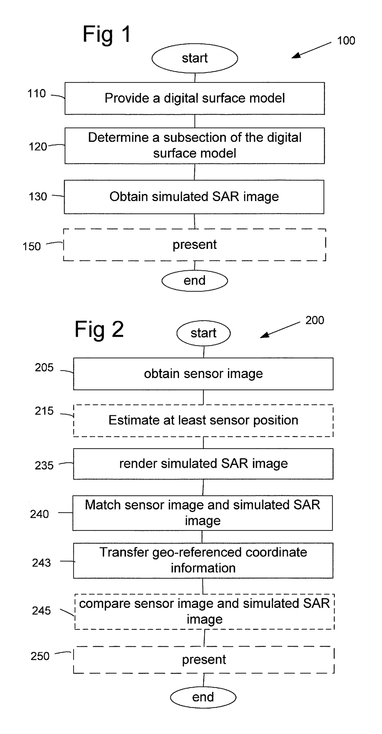
[0055]In FIG. 1, a method 100 for rendering a simulated Synthetic Aperture Radar, SAR, image is illustrated. In the illustrated method, the SAR image is rendered based on a digital surface model or the like comprising 3D coordinate data in a geo-referenced coordinate system. Thus, the simulated SAR image is rendered based on a pre-stored digital surface model. In the example of FIG. 1, the method 100 for rendering a Synthetic Aperture Radar, SAR, image, comprises steps of providing 110 a digital surface model or the like comprising 3D coordinate data in a geo-referenced coordinate system, determining 120 a sub-section of the digital surface model, and obtaining 130 a simulated SAR image based on the sub-section of the digital surface model, wherein substantially each point in the simulated SAR image being associated to a 3D coordinate in the geo-referenced coordinate system. Information related to the obtained simulated SAR image provided is in one example presented 150. In one exam...


PUM


Abstract

The present disclosure relates to a method (100) for rendering a simulated Synthetic Aperture Radar, SAR, image. The method comprises providing (110) a digital surface model or the like comprising 3D coordinate data in a geo-referenced coordinate system, determining (120) a sub-section of the digital surface model, and obtaining (130) the simulated SAR image based on the subsection of the digital surface model, wherein substantially each point in the simulated SAR image being associated to a 3D coordinate in the geo-referenced coordinate system.

Description

CROSS REFERENCE TO RELATED APPLICATIONS[0001]This application is a National Stage Application, filed under 35 U.S.C. §371, of International Application No. PCT / SE2014 / 050459, filed Apr. 14, 2014, the contents of which are hereby incorporated by reference in their entirety.BACKGROUND[0002]Related Field[0003]The present disclosure relates to a method and system for rendering a Synthetic Aperture Radar image.[0004]Description of Related Art[0005]Synthetic-aperture radar, SAR, is a form of radar whose defining characteristic is its use of relative motion, between an antenna and its target region, to provide distinctive long-term coherent-signal variations, that are exploited to obtain finer spatial resolution than possible with conventional beam-scanning means.[0006]SAR is usually implemented by mounting on a moving platform such as an aircraft or spacecraft, a single beam-forming antenna from which a target scene is repeatedly illuminated with pulses of radio waves. Echoes successfully...

Claims


Application Information

Patent Timeline
IPC IPC(8): G01S13/90G06T17/05G06T15/20G06T15/00
CPCG01S13/90G01S13/9035G06T17/05G01S13/9094G06T15/00G06T15/20G01S13/9027
Inventor CARLBOM, PERTOSS, TOMASDAMMERT, PATRIKHAGLUND, LEIF
Owner MAXAR INT SWEDEN AB
Why Eureka
Try Eureka