Electrostatic dust and debris sensor for an engine

a technology engines, applied in the field of dust and debris sensors, can solve the problems of poor signal-to-noise ratio, difficult to accurately assess the condition of the engine at takeoff and climb of the aircraft, and the difficulty of conventional systems

Active Publication Date: 2017-07-25
GENERAL ELECTRIC CO
View PDF46 Cites 8 Cited by
  • Summary
  • Abstract
  • Description
  • Claims
  • Application Information

AI Technical Summary

Benefits of technology

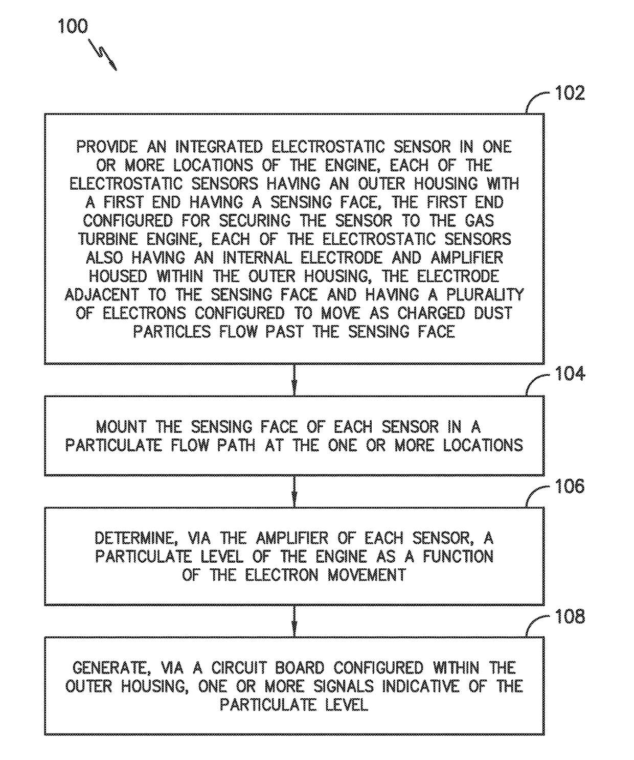
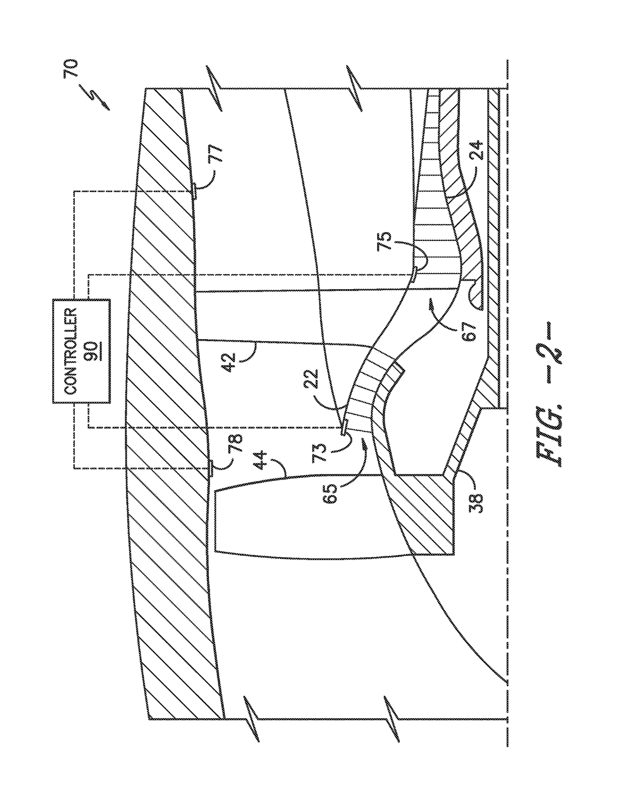
[0007]In one aspect, the present disclosure is directed to an integrated electrostatic sensor for detecting dust and / or debris in an engine, such as an aircraft engine. The sensor includes an outer housing having a body with a first end and a second end. The first end is configured for securing the sensor to the engine and includes a sensing face. The sensor also includes an electrode configured within the housing adjacent to the sensing face and an amplifier configured with the electrode. The electrode contains a plurality of electrons configured to move as charged particles within the engine flow past the sensing face. Thus, the amplifier is configured to detect a particulate level of the engine as a function of the electron movement. The electrostatic sensor also includes a circuit board configured within the outer housing and electrically coupled to the amplifier. As such, the circuit board is configured to send one or more signals to a controller of the engine indicative of the particulate level.

Problems solved by technology

Such data has temporal and special variations as well as error, thereby making accurate assessment of engine conditions at takeoff and climb of the aircraft particularly difficult.
Thus, any motion or vibration of the cabling can produce more charge than the dust or debris particles passing the sensor face, thereby resulting in a poor signal-to-noise ratio.
Further, conventional systems can experience issues due to the triboelectric and piezoelectric effects of the cables and connectors.

Method used


Image

  • Electrostatic dust and debris sensor for an engine
  • Electrostatic dust and debris sensor for an engine
  • Electrostatic dust and debris sensor for an engine

Examples


Embodiment Construction

[0019]Reference now will be made in detail to embodiments of the invention, one or more examples of which are illustrated in the drawings. Each example is provided by way of explanation of the invention, not limitation of the invention. In fact, it will be apparent to those skilled in the art that various modifications and variations can be made in the present invention without departing from the scope or spirit of the invention. For instance, features illustrated or described as part of one embodiment can be used with another embodiment to yield a still further embodiment. Thus, it is intended that the present invention covers such modifications and variations as come within the scope of the appended claims and their equivalents.

[0020]As used herein, the terms “first”, “second”, and “third” may be used interchangeably to distinguish one component from another and are not intended to signify location or importance of the individual components.

[0021]The terms “upstream” and “downstre...


PUM

PropertyMeasurementUnit
operating temperatureaaaaaaaaaa
leakage currentaaaaaaaaaa

Abstract

The present disclosure is directed to an integrated electrostatic sensor for an engine. The sensor includes an outer housing having a body with a first end and a second end. The first end is configured for securing the sensor to the engine and includes a sensing face. The sensor also includes an electrode configured within the housing adjacent to the sensing face and an amplifier configured with the electrode. The electrode contains a plurality of electrons configured to move as charged particles flow past the sensing face. Thus, the amplifier is configured to detect a particulate level as a function of the electron movement. The electrostatic sensor also includes a circuit board configured within the housing and electrically coupled to the amplifier. As such, the circuit board is configured to send one or more signals to a controller of the engine indicative of the particulate level.

Description

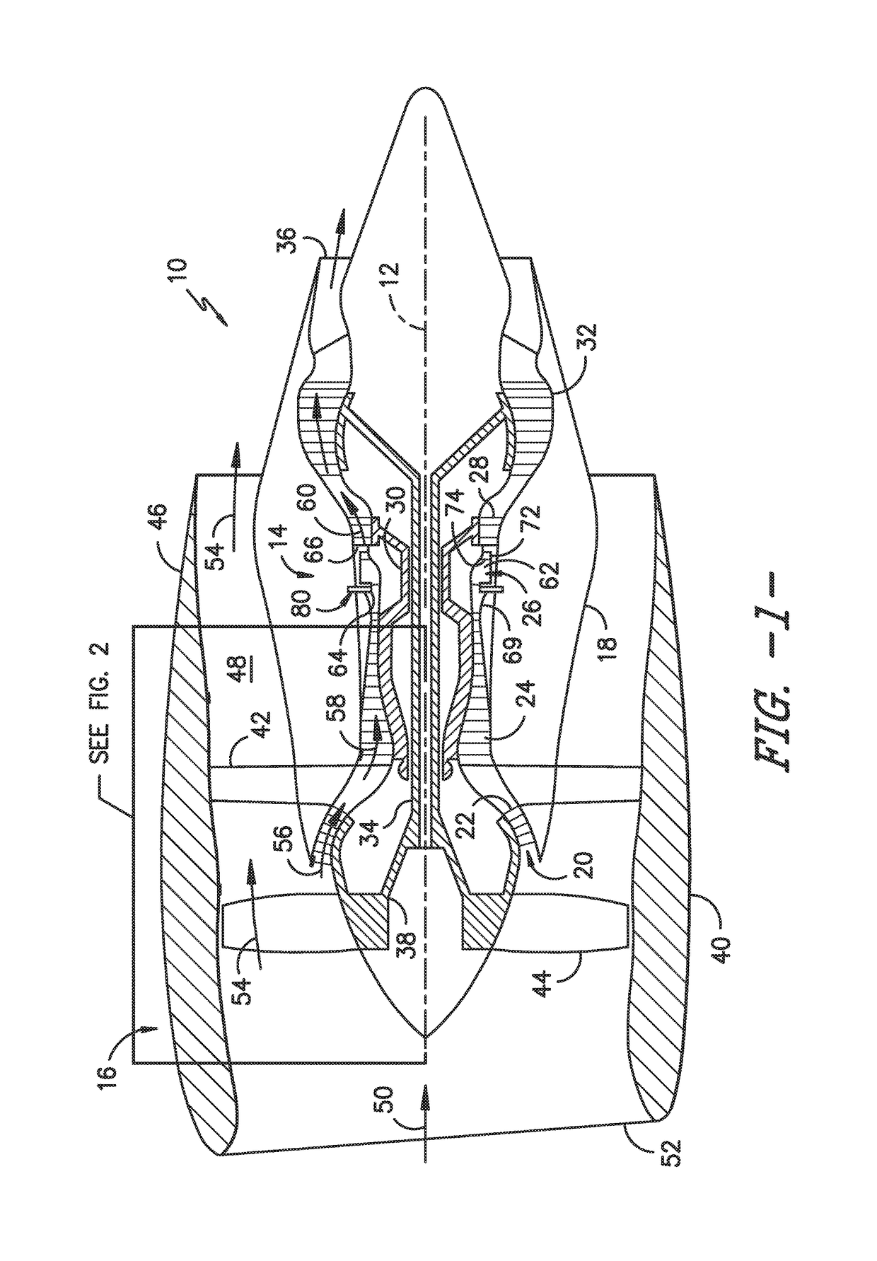
FIELD OF THE INVENTION[0001]The present subject matter relates generally to dust and debris sensors, and more particularly, to electrostatic dust and debris sensors for engines, such as gas turbine engines.BACKGROUND OF THE INVENTION[0002]A gas turbine engine generally includes, in serial flow order, a compressor section, a combustion section, a turbine section and an exhaust section. In operation, air enters an inlet of the compressor section where one or more axial or centrifugal compressors progressively compress the air until it reaches the combustion section. Fuel is mixed with the compressed air and burned within the combustion section to provide combustion gases. The combustion gases are routed from the combustion section through a hot gas path defined within the turbine section and then exhausted from the turbine section via the exhaust section.[0003]In particular configurations, the turbine section includes, in serial flow order, a high pressure (HP) turbine and a low press...

Claims


Application Information

Patent Timeline
Patent Type & Authority Patents(United States)
IPC IPC(8): G01N27/60G01R29/12G01N27/61G01R29/24G01M15/14
CPCG01N27/61G01N27/60G01R29/24G01R29/12G01M15/14G01N15/0656G01N2015/0046G01N15/0266
Inventor WEICKERT, JOHN DAVIDGRIFFIN, GREGORYNOEL, JAMES R.RICKARDS, CHARLES
Owner GENERAL ELECTRIC CO
Why Eureka
Try Eureka