Valve gear for engine

a valve gear and engine technology, applied in the direction of valve details, valve arrangements, machines/engines, etc., can solve the problems of difficult to guarantee performance, difficult to replace, and the above-mentioned camshaft phase varying device cannot operate satisfactorily, so as to improve the abrasion resistance of the constituent components, easy replacement, and easy replacement

Active Publication Date: 2017-08-01
SUZUKI MOTOR CORP
View PDF4 Cites 9 Cited by
  • Summary
  • Abstract
  • Description
  • Claims
  • Application Information

AI Technical Summary

Benefits of technology

[0007]The present invention has been developed to solve the foregoing problems. An object of the invention is to provide a valve gear for an engine capable of easily performing work to confirm and adjust engine speed for changeover or replace constituent components, and easily guaranteeing the performance.
[0010]When the holder is provided thus, the holder can be installed on the camshaft after the constituent components of the camshaft phase varying device have been held in the holder. Accordingly, work to confirm or adjust operation of each constituent component of the camshaft phase varying device can be performed in a stage in which the holder holding the constituent component has not yet been installed on the camshaft. Such a work can be therefore carried out easily and surely. In addition, if a problem is found in a constituent component as a single body in this stage, the component can be replaced as a single body easily and rapidly. It is possible to prevent a variation from occurring in the performance such as engine speed for changeover, durability, reproducibility, etc. due to a variation in frictional force between components touching each other. Thus, the performance can be guaranteed easily.
[0012]When the spline key is thus formed on the holder different from the camshaft so that the guide member can move axially along the spline key, another material high in abrasion resistance than the material of the camshaft can be used for the spline key. Thus, the durability can be improved.
[0017]When the oil supply path is thus formed in the holder so as to communicate with the oil passage in the camshaft, engine oil supplied to the camshaft can be stably supplied to required places in the camshaft phase varying device so as to lubricate the camshaft phase varying device. It is therefore possible to operate the camshaft phase varying device stably and it is also possible to improve the abrasion resistance of the constituent components of the camshaft phase varying device.
[0018]According to the invention, it is possible to obtain various excellent effects such as an effect that engine speed for changeover at which the timings of opening / closing valves should be changed over can be confirmed and adjusted easily or constituent components can be replaced easily, and an effect that the performance can be guaranteed easily.

Problems solved by technology

The aforementioned camshaft phase varying device cannot operate satisfactorily when there is a variation in the centrifugal force acting on the centrifugal weight or the frictional force generated between the driven member and the centrifugal weight and between the guide member and the centrifugal weight during the rotation of cams.
Thus, it takes much labor for such a work.
Thus, there is another problem that it is difficult to guarantee the performance.

Method used


Image

  • Valve gear for engine
  • Valve gear for engine
  • Valve gear for engine

Examples


Embodiment Construction

[0043]A valve gear for an engine according to an embodiment of the invention will be described below with reference to the drawings.

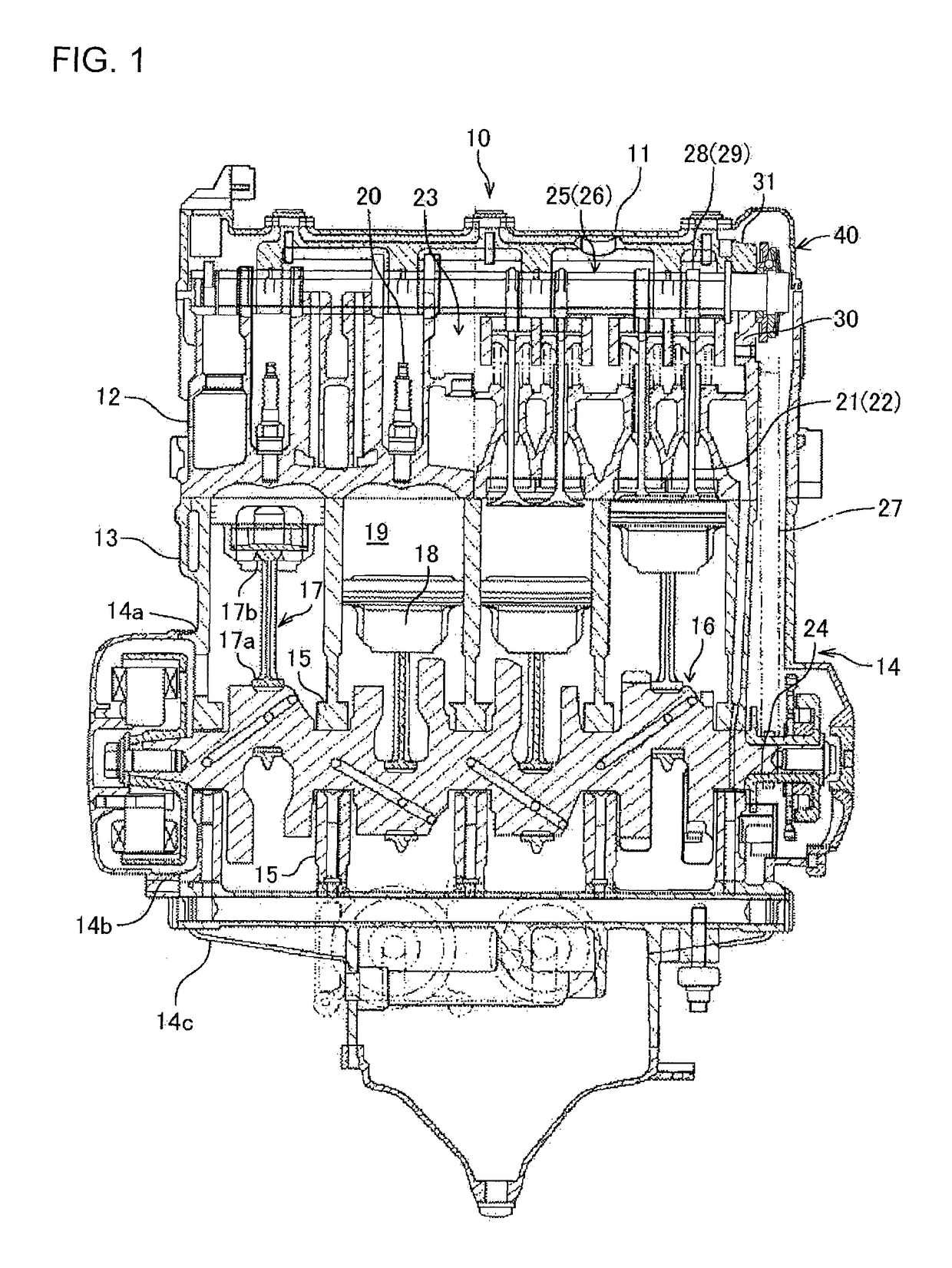
[0044]First, an engine provided with a valve gear according to an embodiment of the invention will be described with reference to FIG. 1. FIG. 1 is a sectional view showing the engine provided with the valve gear according to the embodiment of the invention.

[0045]An engine 10 is, for example, a 4-cycle parallel four cylinder engine, which is mainly constituted by a head cover 11, a cylinder head 12, a cylinder block 13 and an engine case 14. The engine case 14 is vertically divided into three, including an upper engine case 14a, a center engine case 14b and a lower engine case 14c. The cylinder block 13 is formed integrally with the upper engine case 14a.

[0046]The cylinder block 13 is disposed not upright but slightly with a forward inclination. Each of bearing portions 15 is formed to be divided into upper and lower parts on the inner sides of mating ...


PUM


Abstract

A valve gear for an engine, includes: a camshaft phase varying device by which a rotational phase of a camshaft for opening / closing valves of the engine can be changed relatively to that of a crankshaft; and a holder that is provided so that the holder can be removably attached to the camshaft in a state where the holder has held constituent components of the camshaft phase varying device.

Description

FIELD OF THE INVENTION[0001]The present invention relates a valve gear for an engine, and particularly relates to a valve gear for an engine including a camshaft phase varying device for varying the rotational phase of a camshaft relative to a crankshaft.BACKGROUND OF THE INVENTION[0002]Generally a valve gear for opening and closing intake and exhaust valves at timings synchronized with rotation of a crankshaft (that is, at timings when each valve has the same rotational phase as the crankshaft) is placed in an engine. In the engine provided with such a valve gear, however, it has been known that the optimum opening / closing timings of the intake valves and the exhaust valves are, for example, changed in accordance with the running condition of the engine such as the engine speed or the engine load. Recently, it has been therefore proposed an engine including a valve gear provided with a camshaft phase varying device for varying the rotational phase of a camshaft relative to a cranks...

Claims


Application Information

Patent Timeline
Patent Type & Authority Patents(United States)
IPC IPC(8): F01L1/34F01L1/344F01L1/047F01L1/46
CPCF01L1/34403F01L1/047F01L1/46F01L1/053F01L1/344F01L2250/02F01L2810/02F01L2820/035F01L2303/01
Inventor YOSHIMOTO, DAISUKEYOKOTA, SHUICHI
Owner SUZUKI MOTOR CORP
Why Eureka
Try Eureka