Pressure reducing rotor assembly for a pump

a centrifugal pump and rotor assembly technology, applied in the field of centrifugal pumps, can solve the problems of reducing pump efficiency, deleterious effects, high thrust load, etc., and achieve the effect of reducing the deleterious effects of elevated pressure on the operational aspects and reducing the elevated pressur

Active Publication Date: 2017-08-01
SPECIALTY PUMPS & SYST LLC
View PDF20 Cites 4 Cited by
  • Summary
  • Abstract
  • Description
  • Claims
  • Application Information

AI Technical Summary

Benefits of technology

[0009]In a first aspect of the disclosure, a rotor cover for a rotor assembly for a centrifugal pump includes a body having a rotational axis, a center portion about the rotational axis and a peripheral outer portion radially spaced from the center portion, the body further having a first side that, in use, is oriented away from the fluid chamber of a rotor assembly and a second side that, in use, is oriented toward the fluid chamber of a rotor assembly; a fluid inlet portion being located at the center portion of the body and being positioned on the first side of the body; at least one primary channel formed in the body extending from the fluid inlet portion to proximate the peripheral outer portion of the body; and at least one secondary channel formed in the body providing a pathway for fluid to move from a point proximate the second side of the body toward the peripheral outer portion of the body. This aspect of the disclosure presents a rotor cover that is structured to reduce elevated pressure in a rotor assembly, thereby reducing the deleterious effects of the elevated pressure on the operational aspects of the pump.
[0023]In a second aspect, a rotor assembly for a centrifugal pump, includes a rotor having a rotational axis and a peripheral edge; a rotor cover having a rotational axis and a peripheral edge, the rotor cover being releasable secured to the rotor to define a fluid chamber therebetween, the fluid chamber having a peripheral annular portion; and a fluid inlet; at least one primary channel formed in either of the rotor or rotor cover, the at least one primary channel extending from the fluid inlet to proximate the peripheral annular portion of the fluid chamber; and at least one secondary channel formed in the rotor, the rotor cover or both, the at least one secondary channel being positioned in proximity to the rotational axis thereof, and being positioned to provide a pathway for fluid to move from a point proximate the rotational axis of the rotor or rotor cover, and within the fluid chamber, toward the peripheral annular portion of the fluid chamber. The rotor assembly of this aspect provides reduction of increased pressures experienced in the fluid chamber within the rotor assembly which can lead to high thrust loads and other deleterious effects that affect pump operation and efficiencies.
[0030]In a third aspect, a centrifugal pump of the pitot tube type includes a pump casing; a rotor assembly positioned within the pump casing, the rotor assembly further including a rotor having a rotational axis and a peripheral edge, a rotor cover having a rotational axis and a peripheral edge, the rotor cover being releasable secured to the rotor to define a fluid chamber therebetween, the fluid chamber having a peripheral annular portion; a fluid inlet; at least one primary channel formed in either of the rotor or rotor cover, the at least one primary channel extending from the fluid inlet to proximate the peripheral annular portion of the fluid chamber; and at least one secondary channel formed in the rotor, the rotor cover or both, the at least one secondary channel being positioned in proximity to the rotational axis thereof, and being positioned to provide a pathway for fluid to move from a point proximate the rotational axis of the rotor or rotor cover, and within the fluid chamber, toward the peripheral annular portion of the fluid chamber; and a pitot tube assembly having a pitot tube positioned within the fluid chamber of the rotor assembly. This aspect of the disclosure provides advantages over centrifugal pumps of the pitot tube type in providing means for reducing pressure at or near the central portion or rotational axis of the rotor assembly within the fluid chamber to thereby improve pump operation and efficiencies.

Problems solved by technology

As a result of the elevated pressures near the axial center of the rotor assembly, various problems are experienced in the operation of the pump that reduce pump efficiencies.
The most notable problem caused by elevated pressures near and at the axial center of the rotor assembly is high axial thrust, which has deleterious effects of the bearing system of the pump.
The rotor assembly of this aspect provides reduction of increased pressures experienced in the fluid chamber within the rotor assembly which can lead to high thrust loads and other deleterious effects that affect pump operation and efficiencies.

Method used


Image

  • Pressure reducing rotor assembly for a pump
  • Pressure reducing rotor assembly for a pump
  • Pressure reducing rotor assembly for a pump

Examples


Embodiment Construction

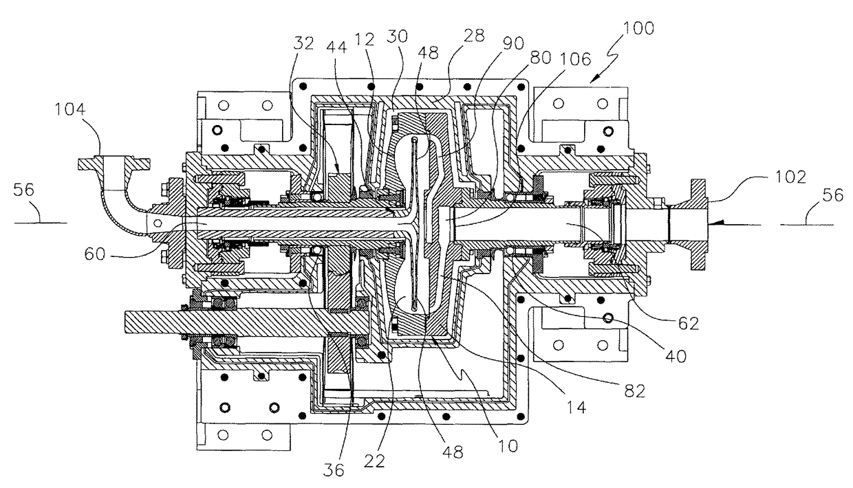
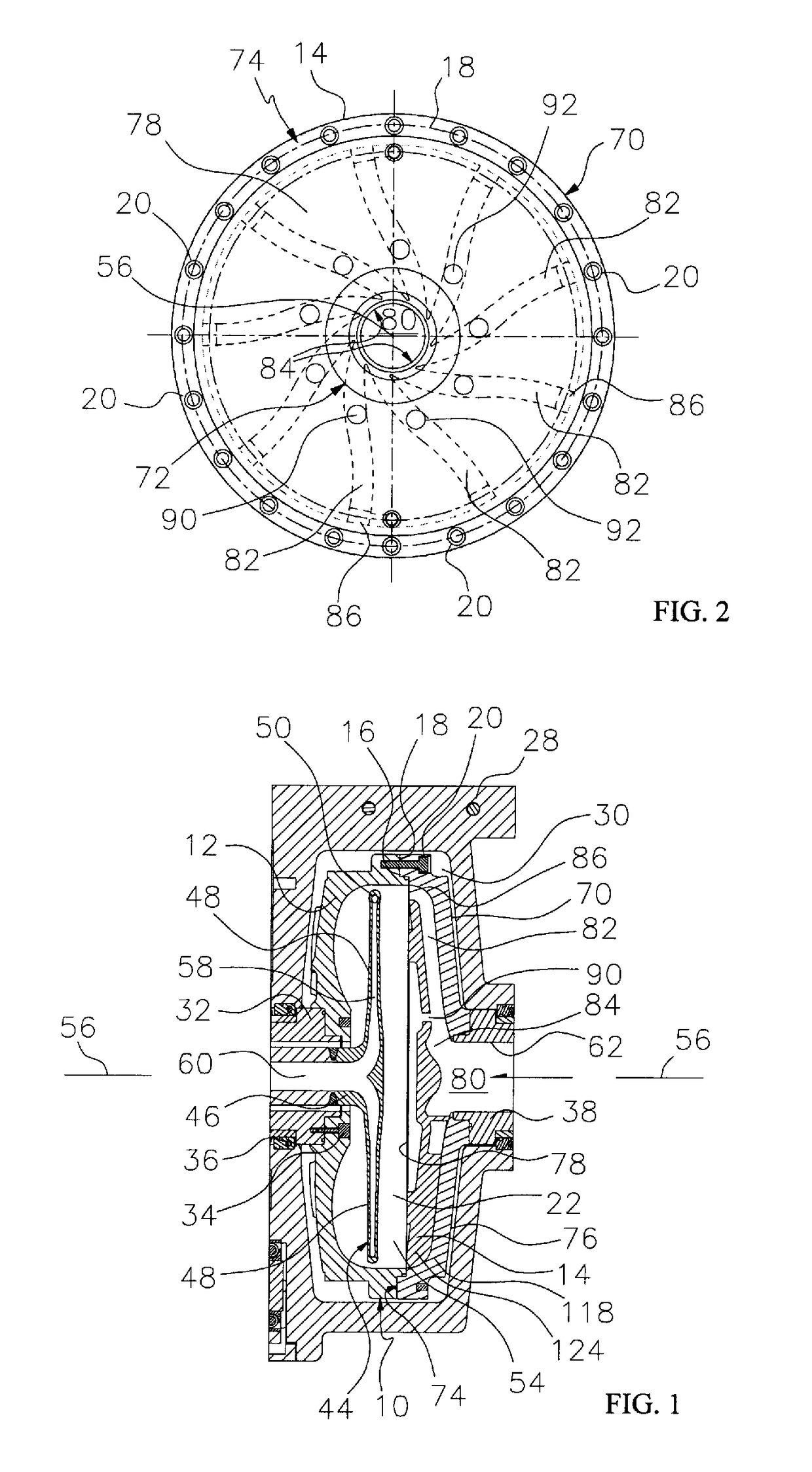
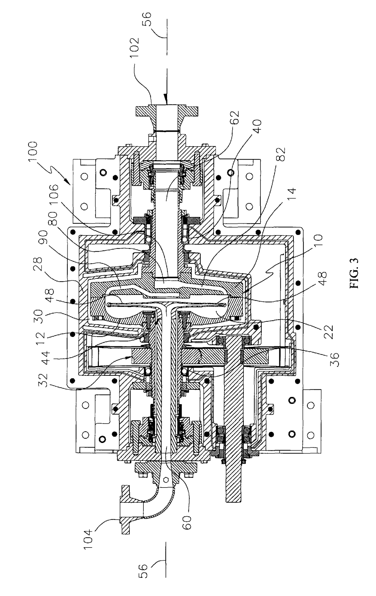
[0049]FIG. 1 generally provides an illustration of a portion of a centrifugal pump of the pitot tube type for the purposes of understanding the general positioning and function of a rotor assembly 10. In FIG. 1, the rotor assembly 10 is comprised of a rotor 12, which is also referred to in the industry as the rotor bowl, and a rotor cover 14. The rotor 12 and rotor cover 14 are releasably secured together about the peripheral edge 16 of the rotor and peripheral edge 18 of the rotor cover by such means as bolts 20, or other suitable securement devices. The joining of the rotor 12 and rotor cover 14 define a fluid chamber 22 therebetween into which fluid is introduced for processing.

[0050]The rotor assembly 10 is positioned within a pump casing 28 and, more specifically, is positioned within a pump chamber 30 formed by the pump casing 28. The rotor assembly 10 is attached to a drive mechanism 32 by known means, such as bolts 34. The drive mechanism 32 is typically supported by bearing...


PUM


Abstract

A rotor assembly for a centrifugal pump includes a rotor and a rotor cover, defining a fluid chamber therebetween, and having openings or channels that are provided in either the rotor cover or the rotor, or both, to direct fluid from the fluid chamber into the rotor or rotor cover of the rotor assembly to provide reduction of increased pressure that is experienced within the fluid chamber, especially at or near the center of the fluid chamber.

Description

CROSS-REFERENCE TO RELATED APPLICATION[0001]This is a non-provisional application that claims priority to U.S. provisional application Ser. No. 62 / 016,749, filed Jun. 25, 2014, the contents of which are incorporated herein in their entirety.TECHNICAL FIELD[0002]This disclosure relates in general to centrifugal pumps and, in particular, to an improved rotor assembly for a centrifugal pump of the pitot type that is configured to provide pressure reduction at the centerline of the rotor assembly to improve pump operation and efficiencies.BACKGROUND OF THE DISCLOSURE[0003]Centrifugal pumps are well known and widely used in a variety of industries to pump fluids or liquid / solid components of fluid mixtures. Centrifugal pumps, particularly those of the pitot tube type, generally comprise a pump housing or pump casing and a rotor assembly positioned within the pump housing which rotates by means of connection to a drive unit. Centrifugal pumps of the pitot tube type have a fluid inlet and ...

Claims


Application Information

Patent Timeline
Patent Type & Authority Patents(United States)
IPC IPC(8): F01D1/12F04D1/12F04D13/14F04D13/12
CPCF04D1/12F04D13/12F04D13/14F04D29/22
Inventor NEILSON, BRYCE
Owner SPECIALTY PUMPS & SYST LLC
Why Eureka
Try Eureka