Ergonomic front fork service tool

a tool and front fork technology, applied in the direction of work benches, cycle equipment, axle suspensions, etc., can solve the problems of difficult removal or installation of fork caps, potential danger, and difficult process, and achieve the effect of safe and convenient servicing of hydraulic front forks

Active Publication Date: 2017-08-08
BLACKFORD WILLIAM
View PDF10 Cites 1 Cited by
  • Summary
  • Abstract
  • Description
  • Claims
  • Application Information

AI Technical Summary

Benefits of technology

[0007]It is therefore an object of the present invention to safely facilitate the servicing of the hydraulic front forks on most American V-Twin motorcycles.
[0008]It is also an object of the present invention to provide a front fork servicing tool which prevents damage to chrome fork tubes of a motorcycle during servicing, and to safely and conveniently mount both front fork tubes to a bench top.
[0009]It is also an object to provide a front fork servicing tool, which can safely release and install a fork tube cap under pressure from the forces of internal compression springs in the front fork tubes.

Problems solved by technology

The inventor having rebuilt numerous front ends to service, add chrome lowers, or tune the front end with optional springs has found the process cumbersome, frustrating, and potentially dangerous.
Removing or installing the fork caps was particularly challenging posing the potential of cross threading and / or damage.
This servicing also posed a safety hazard in the cap flying off as it is under spring pressure.
Other than the use of threaded rod to apply or release pressure, Nolte (FR401769) is very complex and appears to be designed to be used in a repetitive process to apply equal pressure to fasten or remove bolts, rivets etc, as in tamper proof hardware.
The cam device, interchangeable threaded sleeves, and various adapters make this expensive and cumbersome and not useful in servicing front fork tubes of a motorcycle.
Such a step in the spring housing to engage a tool yoke has not been a feature of conventional contemporary motorcycles for some time thereby making Mr. Borner's tool design non-functional on most of today's street motorcycles.

Method used


Image

  • Ergonomic front fork service tool
  • Ergonomic front fork service tool
  • Ergonomic front fork service tool

Examples


Embodiment Construction

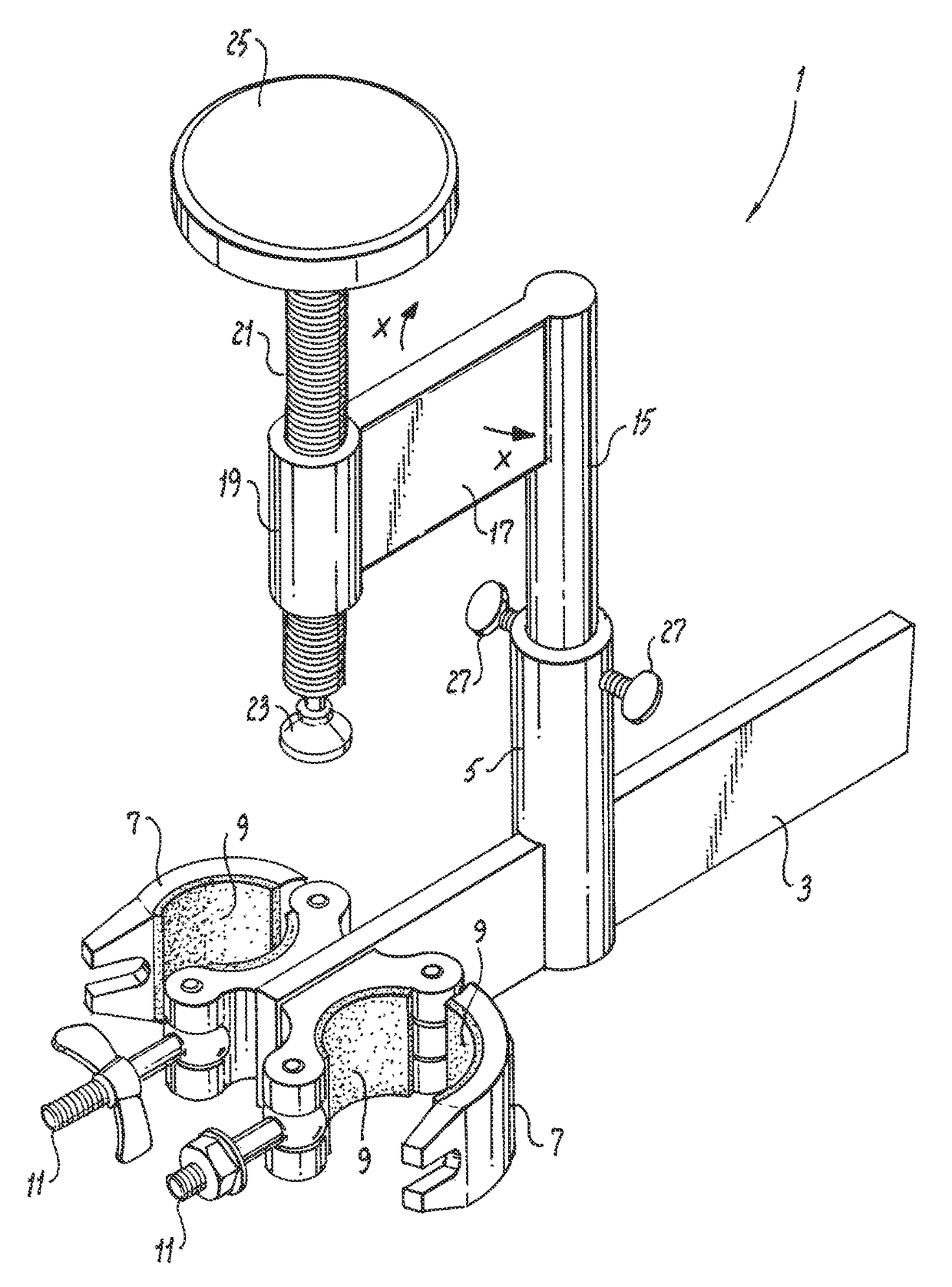
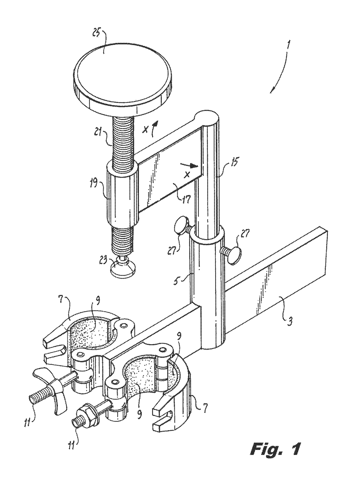
[0043]The various parts of the ergonomic front fork service tool 1 can be identified in FIG. 1. Base bar 3 supports tool 1. Distal tail end (of bar 3) past support tube 5 is typically engaged in a bench vice. The forward end of bar 3 is attached to two swinging gate clamps 7 with fasteners, such a locking eyebolts and nuts 11. Since clamps 7 can use either a wing nut or a hex nut as the tightening element 11, one of each type is illustrated in FIGS. 1 and 2. The inside surface 9 of both clamps 7 is lined with a layer of rubber or a similar non-marring material. Long screw 21 is engaged in threaded housing 19; screw 21 preferably has a large hand knob 25 at its top end and a swiveling foot 23 with a flat bottom at its lower end. Swinging arm 17 attaches housing 19 to column 15. Two thumb screws 27 are shown to lock column 15 in its desired position for the task at hand. Note that arm 17 can be swung in registration with the center of either swinging gate clamp 7 or totally to the rea...


PUM


Abstract

An ergonomic front fork service tool for servicing front fork tubes of a motorcycle includes a long threaded screw engaged in a threaded housing with a swivel foot at the bottom end and a large hand knob at the top end. The threaded housing is attached to a swinging arm attached to a vertical rod support. A base bar has a hollow tube attached at a right angle a distance away from its distal end, which receives and supports the vertical rod while permitting both swinging of the arm and vertical adjustment. The position between the rod and tube is locked by fasteners threaded transversally in the top wall of the tube. A portion of the base bar is used to support the service tool in a bench vise, or to fasten to a work bench, and two swinging gate clamps engage two front fork tubes and rigidly attach them during service to the bench top vertically.

Description

RELATED APPLICATIONS[0001]This application claims benefit and priority under 35USC 119 (e) from provisional application Ser. No. 62 / 275,082 filed Jan. 5, 2016. The '082 application is incorporated by reference herein.FIELD OF THE INVENTION[0002]The present invention relates to a tool for servicing front forks of a motorcycle.BACKGROUND OF THE INVENTION[0003]The purpose of this tool is to safely facilitate the servicing of the hydraulic front forks on most American V-Twin motorcycles.[0004]The inventor having rebuilt numerous front ends to service, add chrome lowers, or tune the front end with optional springs has found the process cumbersome, frustrating, and potentially dangerous. Removing or installing the fork caps was particularly challenging posing the potential of cross threading and / or damage. This servicing also posed a safety hazard in the cap flying off as it is under spring pressure. Also noted was the potential for saving significant time in the process by using the feat...

Claims


Application Information

Patent Timeline
Patent Type & Authority Patents(United States)
IPC IPC(8): B25B27/00B25H1/00B25B27/30B62K25/08
CPCB25B27/0035B25B27/304B25H1/0014B62K25/08B25B5/003
Inventor BLACKFORD, WILLIAM
Owner BLACKFORD WILLIAM
Why Eureka
Try Eureka