
Cutting eye needle

a cutting needle and eye needle technology, applied in the field of sewing needles, can solve the problems of ineffective cutting surfaces of needle eye blades in the conventional manufacture of needles through traditional stamping processes

Inactive Publication Date: 2017-08-08
PARKER DOUGLAS DOUG
View PDF18 Cites 0 Cited by
  • Summary
  • Abstract
  • Description
  • Claims
  • Application Information

AI Technical Summary

Benefits of technology

The present invention is about a needle with a cutting edge. It has a tip connected to an elongated portion and an eye connected to the elongated portion opposite the tip. The needle is manufactured through a process called injection molding, which involves using machines in commercial polymer processing plants. The patent text explains the process of injection molding and its benefits. The technical effect of this invention is the production of a needle with a cutting edge that can be easily manufactured using injection molding.

Problems solved by technology

Conventional manufacture of needles through traditional stamping processes produces ineffective cutting surfaces within the needle eye.

Method used


Image

  • Cutting eye needle
  • Cutting eye needle
  • Cutting eye needle

Examples


embodiment

Preferred Embodiment

[0025]Manufacturing of the needle of the present invention involves the process of injection molding which is commonly known to anyone skilled in the field. The needle of the present invention can be manufactured of various types of materials such as metals, ceramics, or plastics common to the injection molding process.

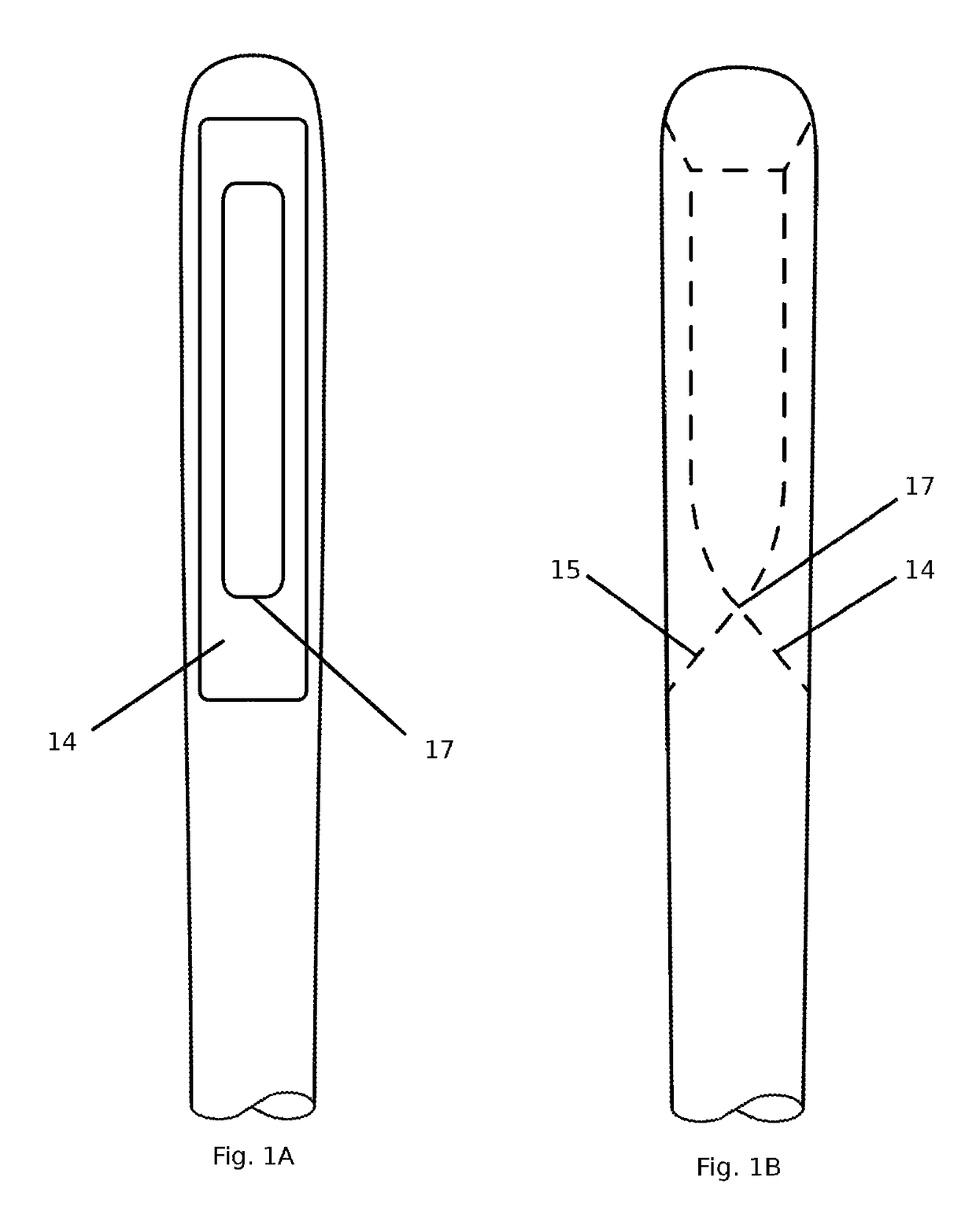
[0026]To cut one or more threads using a needle of the present invention, one first pulls on its threaded thread ends to tension the thread. One then slides an eye portion of the needle to a location along the threaded thread, and presses edge 17 against the tensioned thread, cutting the thread.

[0027]In difficult-to-reach areas of a sewing project between its two backings, one initially pushes the needle through a first penetration point of the backing into a cavity between the two backings One next pulls the needle through the cavity between the backings. One then pushes the needle's tip and elongated portions into view through a second point in t...


PUM


Abstract

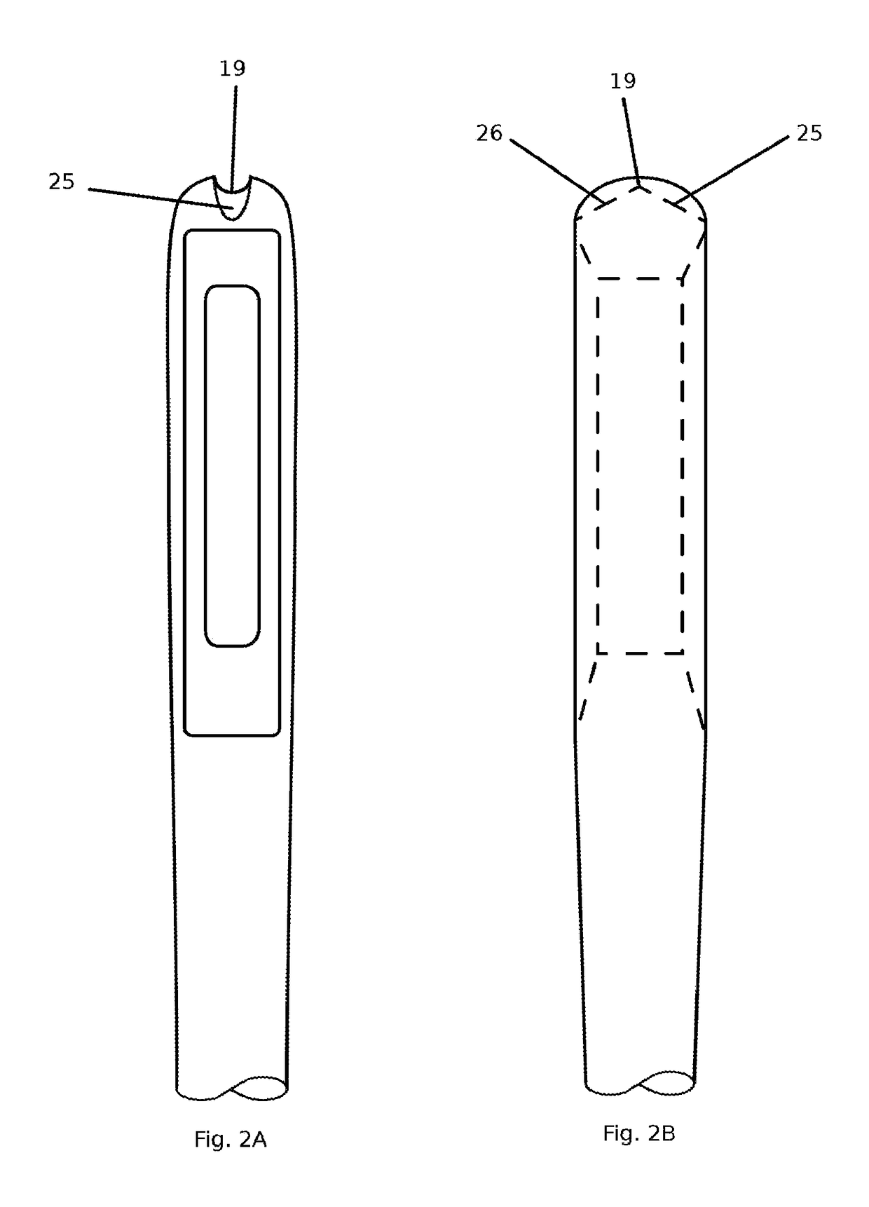
Cutting eye needle comprising an elongated portion, a tip portion, and an eye portion comprising a frictionally engaged cutting edge, with adjacent surfaces (14) and (15) intersecting at edge (17) at an angle that creates a frictionally engaged cutting edge, which threads and sews like a conventional hand sewing needle, which is suitable for cutting one or more threads, in professions including the medical field and surgery, and in needlecraft operations particularly suited to quilting, where ends of thread are cut while located inside the cavities of a quilting project, while simultaneously reducing the probability of skin contact of an operator are disclosed.

Description

CROSS-REFERENCE TO RELATED APPLICATIONS[0001]This application claims the benefit of provisional patent application for Ser. No. 61 / 699692, filed 2012 Sep. 11 by the present inventor.FEDERALLY SPONSORED RESEARCH[0002]Not ApplicableSEQUENCE LISTING OR PROGRAM[0003]Not ApplicableBACKGROUND OF THE INVENTION[0004]Field of the Invention[0005]The present invention relates generally to a sewing needle. More specifically, the invention is a sewing needle that incorporates an eye portion comprising a cutting edge.[0006]Prior Art[0007]A quilter quilting a project by hand or by machine will use a number of lengths of thread to sew the project together. When the end of a length of thread becomes too short to continue sewing, the quilter will be left with a tail end of thread visible on a front face (here also called a backing) or a back backing of the project. It is desirable for the quilter to hide the tails of thread between the front and back backings of the project.[0008]Using a standard, ha...

Claims


Application Information

Patent Timeline
Patent Type & Authority Patents(United States)
IPC IPC(8): A61B17/06D05B85/00A61B17/04
CPCD05B85/00A61B17/0467A61B17/06A61B17/06066A61B2017/06019
Inventor PARKER, DOUGLAS "DOUG"
Owner PARKER DOUGLAS DOUG
Learn More