Camera and camera accessory

a technology for cameras and accessories, applied in the field of cameras, can solve the problems of hindering the reduction of the need of increasing the pitch between the contact pins, and the increase of the angular range, so as to reduce the angular range occupied by the contact pins, reduce the loss, and reduce the size of the camera

Active Publication Date: 2017-08-08
CANON KK
View PDF76 Cites 2 Cited by
  • Summary
  • Abstract
  • Description
  • Claims
  • Application Information

AI Technical Summary

Benefits of technology

[0011]The present invention is directed to a camera and a camera accessory capable of reducing an angular range occupied by contacts at amount, so that a size of the camera can be reduced. Further, the present invention is directed to a camera and a camera accessory capable of reducing a loss due to a wiring resistance regarding power supply, and further, impervious to noises.

Problems solved by technology

There are following problems in the camera and the accessory having the mounts (especially, the molded mounts) provided with the contact pins as described above.
However, in a case where the camera-side contact pin is provided at the same position as the fastening screw in a mount circumferential direction, and the plate spring is used as the contact spring for biasing the camera-side contact pin in the projecting direction, the plate spring should be disposed so as to avoid the fastening screw, which leads to the necessity of increasing a pitch between the contact pins.
This results in an increase in an angular range occupied by the contact pins at the mount, hindering a reduction in the size of the camera.
On the other hand, the camera includes a motor as an actuator for driving, for example, a shutter, and noises generated by this motor may affect control of the lens-side accessory which causes a malfunction of the accessory.
If the length of this wiring is long, a loss due to a wiring resistance may increase.

Method used


Image

  • Camera and camera accessory
  • Camera and camera accessory
  • Camera and camera accessory

Examples


Embodiment Construction

[0051]Various exemplary embodiments, features, and aspects of the invention will be described in detail below with reference to the drawings.

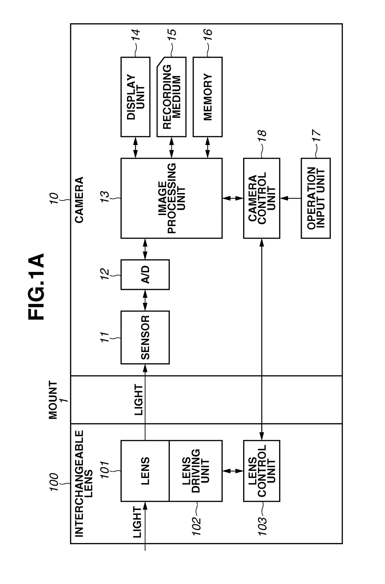
[0052]FIG. 1A illustrates a camera system including an interchangeable lens 100 as a camera accessory according to a first exemplary embodiment of the present invention, and a camera 10 with the interchangeable lens 100 detachably mounted thereon. The camera 10 and the interchangeable lens 100 each include a mount 1 having electric contacts for supplying power from the camera 10 to the interchangeable 100, and allowing communication between the camera 10 and the interchangeable lens 100. In the present exemplary embodiment, the interchangeable lens 100 will be described as a camera accessory mountable onto the camera 10, but camera accessories other than the interchangeable lens 100 are also included in the present invention as other exemplary embodiments.

[0053]The camera 10 includes an image sensor 11 configured to output an electric signal by...


PUM


Abstract

The present invention provides the following camera. A first camera-side contact pin is a pin corresponding to detection of a signal change caused by coupling of a camera accessory. A second camera-side contact pin is a pin corresponding to supply of power for communication with the coupled camera accessory. A third camera-side contact pin is a pin corresponding to supply of a driving force to an actuator of the camera accessory. The first, second, and third camera-side contact pins are disposed in such a manner that, when a camera-side mount shifts from a first state to a second state, the third camera-side contact pin contacts first and second accessory-side contact surfaces, the second camera-side contact pin contacts the first accessory-side contact surface, and the first camera-side contact pin does not contact the second and third accessory-side contact surfaces.

Description

TECHNICAL FIELD[0001]The present invention relates to a camera, and a camera accessory such as an interchangeable lens interchangeably mounted on the camera.BACKGROUND ART[0002]A camera accessory (hereinafter referred to just as an accessory) receives power supply from a camera and exchanges a command, data, and the like with the camera in a state mounted on the camera. A plurality of contacts, which is electrically connected by making a contact with each other, is formed at mounting portions (mounts) of the camera and the accessory to allow the power supply and communication. Further, in many cases, a bayonet coupling method is employed for attachment (coupling) between the camera and the accessory. According to the bayonet coupling method, a relative rotation is performed between the mounts of the camera and the accessory to engage bayonet teeth provided on the respective mounts with each other.[0003]Japanese Patent Application Laid-Open No. 62-195633 discusses a camera and an int...

Claims


Application Information

Patent Timeline
Patent Type & Authority Patents(United States)
IPC IPC(8): H04N5/68G03B17/14H04N5/225G03B17/00G02B13/16H04N5/232G03B17/56
CPCH04N5/2254G03B17/14G03B17/565H04N5/23209G03B2206/00H04N23/663
Inventor TOKUNAGA, TATSUYUKIHASEGAWA, TAKASHINISHIO, TETSUYAKONNO, YOSHIHIKOKIKUCHI, HIROSHISUGAWARA, AZUSA
Owner CANON KK
Why Eureka
Try Eureka