Endoillumination using decentered fiber launch

a fiber launch and endo-illumination technology, applied in the field of microsurgical probes, can solve the problems of difficult to discard after one or only a few surgical procedures, most of the prior art devices have a cost, and the current state of the art probes are quite complex in operation

Active Publication Date: 2017-08-15
ALCON INC
View PDF16 Cites 1 Cited by
  • Summary
  • Abstract
  • Description
  • Claims
  • Application Information

AI Technical Summary

Benefits of technology

[0007]According to particular embodiments of the present invention, an endoilluminator system includes an endoilluminator probe and an illumination source. The endoilluminator probe includes a nano-scale optical fiber and a probe fiber connector, and the illumination source includes a source fiber connector. The illumination source is configured to produce an illumination spot at the source fiber connector having a diameter smaller than a diameter of a fiber core of the nano-scale optical fiber. The probe fiber connector and the source connector are configured when connected to align the illumination spot off-center relative to the nano-scale optical fiber such that the angular distribution of light emitted by the nano-scale optical fiber is increased relative to aligning the illumination spot at a center of the nano-scale optical fiber.

Problems solved by technology

Current state of the art probes are quite complex in operation, often times requiring moving parts that are operated using complex mechanical systems.
Most of the prior art devices have a cost that makes them difficult to discard after one or only a few surgical procedures.
Furthermore, the complexity of prior art devices leads generally to probes having cross sections of several millimeters.
These probes are of little practical use for ophthalmic microsurgical techniques.
Because of the relatively small aperture, endoilluminators for the interior of the eye face additional challenges.
Both of these considerations have made it difficult to produce small gauge endoilluminators.

Method used


Image

  • Endoillumination using decentered fiber launch
  • Endoillumination using decentered fiber launch
  • Endoillumination using decentered fiber launch

Examples


Embodiment Construction

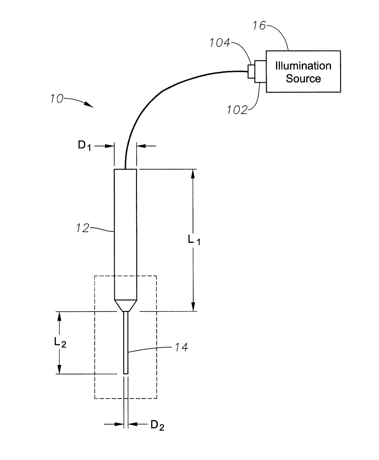
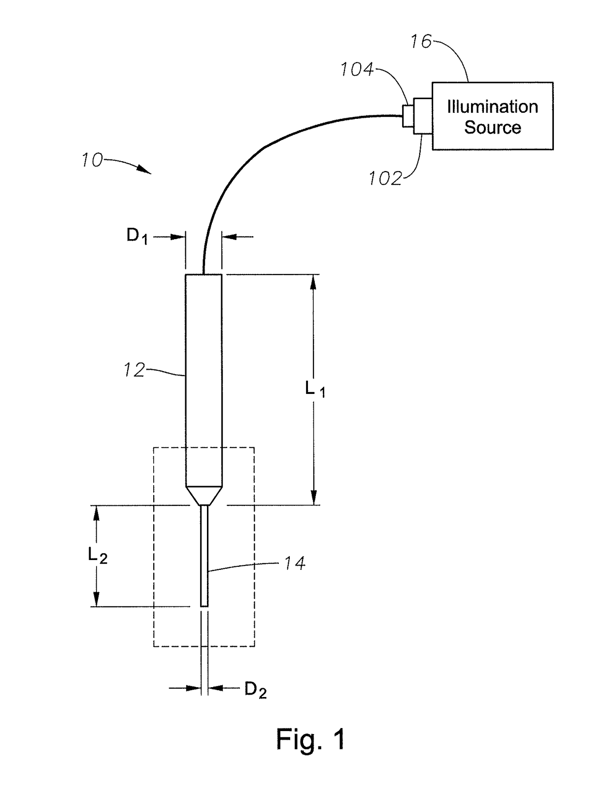
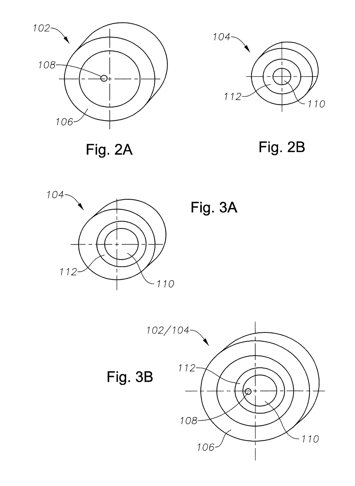
[0015]Various embodiments of the present invention provide a fiber connector system with a decentered launch of light beams into the probe optical fiber. Certain embodiments include a source fiber connector and a probe fiber connector, wherein an illumination spot emitted from the source fiber connector is offset from a center of the probe fiber. For example, the connectors can hold the central axes of the source emitter and the probe fiber offset relative to one another. In another example, the source emitter can be configured to emit an illumination spot off center relative to the probe fiber. Additional features of various embodiments of the present invention are described in the following explanation of the FIGs.

[0016]Various embodiments of the present invention provide improve endoillumination by increasing the angular distribution of the illuminated area using a decentered launch while providing equivalent or greater coupling efficiency for the illumination source to the probe...


PUM


Abstract

An endoilluminator system includes an endoilluminator probe and an illumination source. The endoilluminator probe includes a nano-scale optical fiber and a probe fiber connector, and the illumination source includes a source fiber connector. The illumination source is configured to produce an illumination spot at the source fiber connector having a diameter smaller than a diameter of a fiber core of the nano-scale optical fiber. The probe fiber connector and the source connector are configured when connected to align the illumination spot off-center relative to the nano-scale optical fiber such that the angular distribution of light emitted by the nano-scale optical fiber is increased relative to aligning the illumination spot at a center of the nano-scale optical fiber.

Description

RELATED APPLICATIONS[0001]This application claims priority to U.S. provisional application Ser. No. 61 / 521,450 , filed on Aug. 9, 2011, the contents which are incorporated herein by reference.BACKGROUND[0002]1. Field of the Invention[0003]Embodiments described herein relate to the field of microsurgical probes. More particularly, embodiments described herein are related to the field of endoillumination using decentered fiber launch.[0004]2. Description of Related Art[0005]The field of microsurgical procedures is evolving rapidly. Typically, these procedures involve the use of probes that are capable of reaching the tissue that is being treated or diagnosed. Such procedures make use of endoscopic surgical instruments having a probe coupled to a controller device in a remote console. Current state of the art probes are quite complex in operation, often times requiring moving parts that are operated using complex mechanical systems. In many cases, an electrical motor is included in the...

Claims


Application Information

Patent Timeline
Patent Type & Authority Patents(United States)
IPC IPC(8): F21V5/00A61B1/07G02B6/42A61B90/30A61B3/00G02B6/36A61B1/00
CPCA61B1/07A61B3/0008A61B90/30G02B6/4206A61B1/0017A61B2090/306F04C2270/041G02B6/3624
Inventor YADLOWSKY, MICHAEL J.PAPAC, MICHAEL
Owner ALCON INC
Why Eureka
Try Eureka