Sealing system for a vacuum cleaner suction pipe

a vacuum cleaner and suction pipe technology, applied in the direction of fluid pressure sealing joints, applications, sleeve/socket joints, etc., can solve the problems of insufficient assurance of the controllability of the vacuum cleaner suction pipe by the operator, the requirement of system tightness is not met, and the challenge always arises

Active Publication Date: 2017-08-15
FISCHER ROHRTECHN
View PDF27 Cites 1 Cited by
  • Summary
  • Abstract
  • Description
  • Claims
  • Application Information

AI Technical Summary

Benefits of technology

[0006]Therefore, a primary object of this invention is to devise a sealing system which ensures maximum possible sealing with simultaneously simple operator controllability of the vacuum cleaner suction pipe.

Problems solved by technology

Here, the challenge always arises that the displacement of the inner pipe relative to the outer pipe with the best possible sealing must be able to be take place with little effort and in a simple manner in order to not adversely affect the operator controllability of the vacuum cleaner suction pipe.
Sealing systems known from the prior art for vacuum cleaner suction pipes have the disadvantage that either the requirements for the tightness of the system are not achieved or simple operator controllability of the vacuum cleaner suction pipe is not adequately ensured.

Method used


Image

  • Sealing system for a vacuum cleaner suction pipe
  • Sealing system for a vacuum cleaner suction pipe
  • Sealing system for a vacuum cleaner suction pipe

Examples


Embodiment Construction

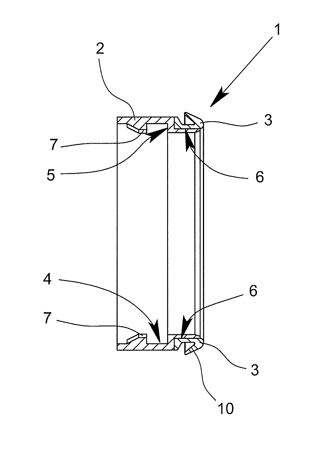
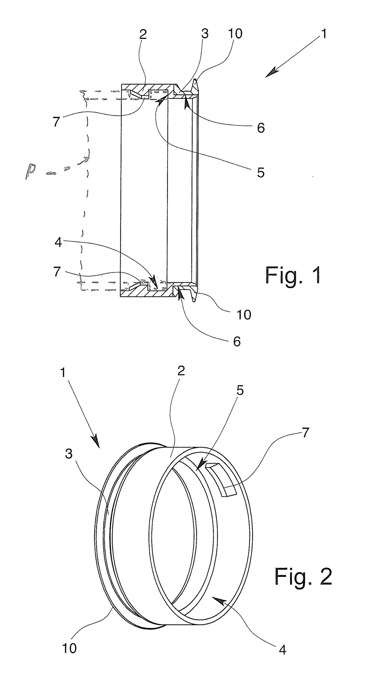
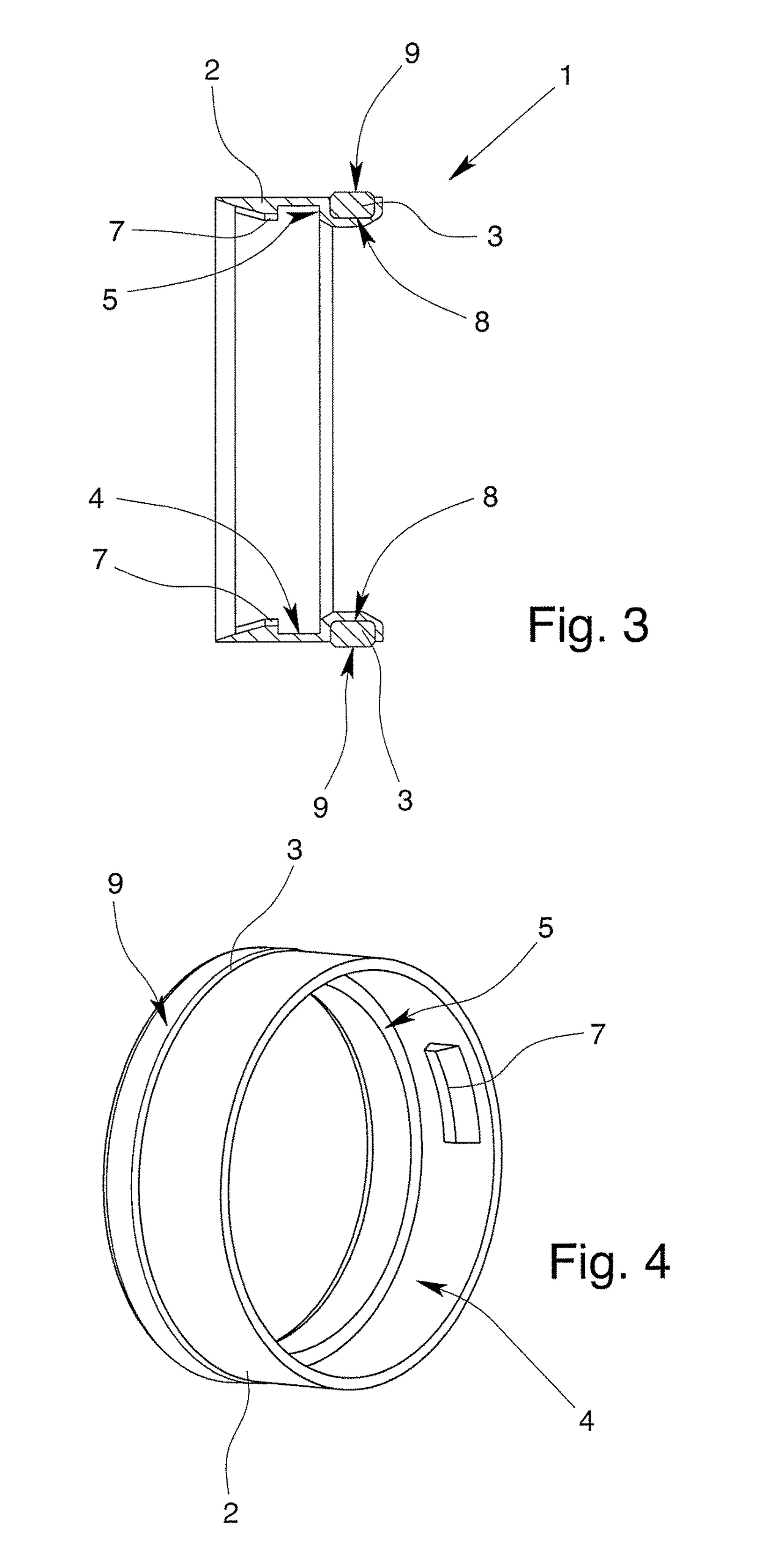
[0031]FIG. 1 shows an exemplary embodiment of a sealing system 1 for sealing between an inner pipe and an outer pipe of a telescoping vacuum cleaner suction pipe P (an end portion of which is shown in phantom outline). The sealing system 1 comprises an annular base body 2, the base body 2 being produced from a first material. The sealing system 1 also comprises an annular sealing body 3 which is located on the base body 2, the sealing body 3 being produced from a second material. The first material and the second material are different materials which however can originate from the same material super group.

[0032]The sealing body 3 is located on the base body 2 so that the base body 2 and the sealing body 3 form a unit, specifically the sealing system 1. The sealing body 3 extends partially on an outer periphery of the base body 2. Both the base body 2 and also the sealing body 3 have an annularly closed contour. The base body 2 on its inner periphery has an inner shoulder 4 so that...


PUM


Abstract

A sealing system (1) for sealing between an inner pipe and an outer pipe of a telescoping vacuum cleaner suction pipe, which ensures maximum possible sealing with simultaneously simple operator controllability of the vacuum cleaner suction pipe, has at least one annular base body (2) of a first material and an annular sealing body (3) of a second material on the base body (2).

Description

BACKGROUND OF THE INVENTION[0001]Field of the Invention[0002]The invention relates to a sealing system for sealing between an inner pipe and an outer pipe of a telescoping vacuum cleaner suction pipe, comprising at least one annular base body of a first material.[0003]Description of Related Art[0004]Vacuum cleaner suction pipes whose length can be adjusted by displacing an inner pipe relative to an outer pipe are known in the prior art in a host of configurations. The inner pipe and the outer pipe form a suction channel between, for example, a floor nozzle and the suction hose of the vacuum cleaner. The vacuum cleaner causes a negative pressure which induces the suction effect on the floor nozzle. To prevent penetration of secondary air into the suction channel in the operating state, and thus, to increase the energy efficiency of the vacuum cleaner, sealing of the transition region between the inner pipe and the outer pipe is necessary. The inner pipe is routed within the outer pip...

Claims


Application Information

Patent Timeline
Patent Type & Authority Patents(United States)
IPC IPC(8): A47L9/24F16J15/10F16J15/02
CPCF16J15/02A47L9/244F16J15/104A47L9/24
Inventor CORDES, MARTINCORDES, STEPHAN
Owner FISCHER ROHRTECHN
Why Eureka
Try Eureka