Loading and/or unloading device for a freeze drying system

Active Publication Date: 2017-08-22
MARTIN CHRIST GEFRIERTROCKNUNGSANLAGEN
View PDF21 Cites 0 Cited by
  • Summary
  • Abstract
  • Description
  • Claims
  • Application Information

AI Technical Summary

Benefits of technology

[0019]A further advantage which arises from the use of the system of supports, in particular the provision of a height position—independent of the frame—of a utility surface resides in the fact that e.g. in the unloading position the vertical distance between the utility surfaces can be adapted to the height of the drying vessels. Sealing the drying vessels in a vacuum by means of rubber stoppers is known, by means of which, after the stoppers have been inserted, they can adhere to the utility surfaces which are located above them in eac

Problems solved by technology

Nowadays, it is impossible or very expensive to upgrade a freeze drying plant, which is to be loaded and/or unloaded manually, to an integrated automated

Method used


Image

  • Loading and/or unloading device for a freeze drying system
  • Loading and/or unloading device for a freeze drying system
  • Loading and/or unloading device for a freeze drying system

Examples


Embodiment Construction

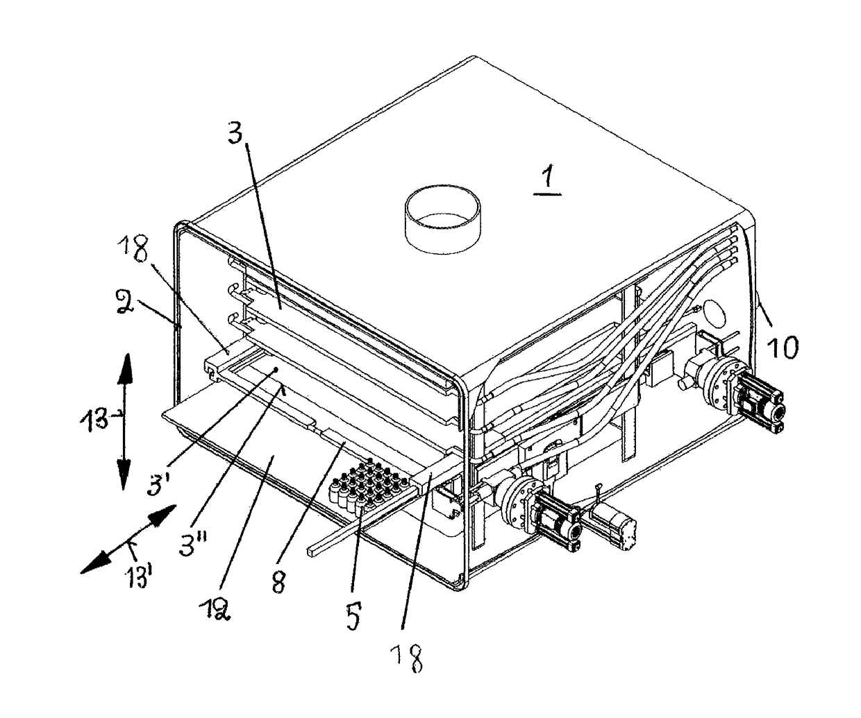
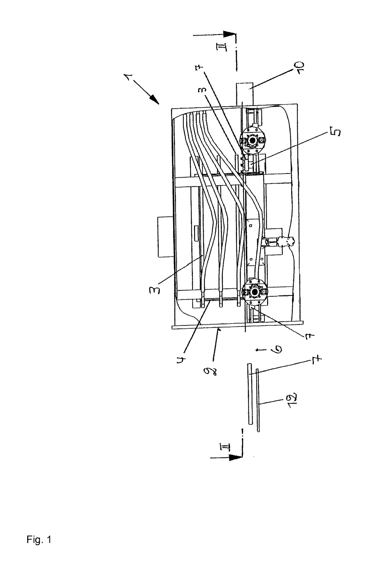
[0030]FIG. 1 illustrates a sectional view of the drying chamber 1 of a freeze drying system, in whose front side 2 there is located a closable opening, not shown in the drawings, for loading or unloading drying vessels 5. The drying chamber 1 is connected to a condenser chamber in a manner known per se, however this will not be explained in greater detail at this juncture.

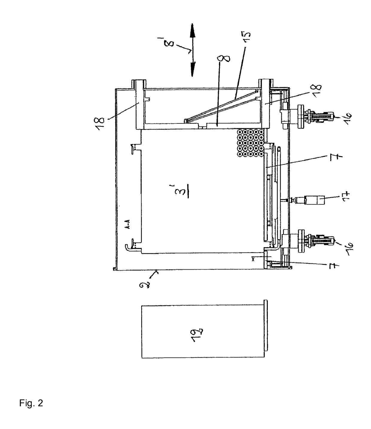
[0031]Located inside the drying chamber 1 is an arrangement of utility surfaces 3 which are held in a frame 4 in a manner known per se so as to be vertically movable. These utility surfaces 3 are used for positioning drying vessels 5 which each contain a substance to be dried and which are to be removed from the drying chamber 1 upon completion of the drying procedure. The reference numeral 6 designates a height position, in this case the utility surface 3′ which corresponds to the unloading position of this utility surface. It is essential that the vertical adjustability of all of the utility surfaces 3 of the fra...


PUM


Abstract

A device for loading and unloading the utility surface (3′) of a drying chamber (2) of a freeze drying system. The device includes a carriage (8) which forms a movable guiding edge for the drying vessels (5), and is moveable on guides (7) disposed on both sides of the utility surface (3) and which extend in parallel with the movement direction and form fixed guiding edges for the drying vessels (5). At least one linear motor is provided to produce a drive for the carriage. All of the components of the device can be located inside the drying chamber (1), and the device of the present invention is suitable for upgrading existing freeze drying systems.

Description

FIELD OF THE INVENTION[0001]The invention relates to a loading and / or unloading device for a freeze drying system for pushing drying vessels, which contain a product to be dried and stand on one of the plurality of utility surfaces of the drying chamber of the freeze drying system, in a movement direction for the purpose of unloading or loading the utility surface through at least one opening in the wall of the drying chamber, having a carriage which forms a guiding edge movable in the movement direction, is intended to exert a feeding action upon the drying vessels and is supported so as to be movable on guides which are disposed inside the drying chamber on both sides at a spaced interval from the utility surface to be loaded or unloaded, are in parallel with one another and with the movement direction and form guiding edges.BACKGROUND OF THE INVENTION[0002]A device of this type is already known from German patent application 10 2009 049 142.2-16 by the Applicant dated Oct. 12, 20...

Claims


Application Information

Patent Timeline
IPC IPC(8): F26B13/30F26B5/06F26B25/00
CPCF26B25/001F26B5/06F26B25/003
Inventor CHRIST, MARTIN
Owner MARTIN CHRIST GEFRIERTROCKNUNGSANLAGEN
Why Eureka
Try Eureka