
Cable conveyor disc

a conveyor disc and cable technology, applied in the direction of conveyors, transportation and packaging, etc., can solve the problems of limiting the efficiency of the system, and achieve the effect of easy removal for quick replacement and cleaning

Active Publication Date: 2017-08-29
INTRACO
View PDF9 Cites 5 Cited by
  • Summary
  • Abstract
  • Description
  • Claims
  • Application Information

AI Technical Summary

Benefits of technology

The present invention is a close tolerance disc for a flexible member conveyor, which includes a disc body and a movable resilient ring made of durable polymer interlocking ring. The ring bends to match the inside surface of the conveyor tubing, ensuring 100% conveyance of the material in the system. The ring moves within a groove in the body of the disc and can adjust to the irregularities in the manufacturing process of the conveyor tubular components. The ring is easy to remove for replacement and cleaning. The interlocking ends keep the ring ends in place, preventing misalignment while passing through a partially cutaway portion of the tube. Overall, this invention improves the efficiency and reliability of material conveyance in flexible member conveyor systems.

Problems solved by technology

When the conveyed material has a small particle size, material can pass through the gap between the disc and the tube wall, thus limiting the efficiency of the system.

Method used


Image

  • Cable conveyor disc
  • Cable conveyor disc
  • Cable conveyor disc

Examples


Embodiment Construction

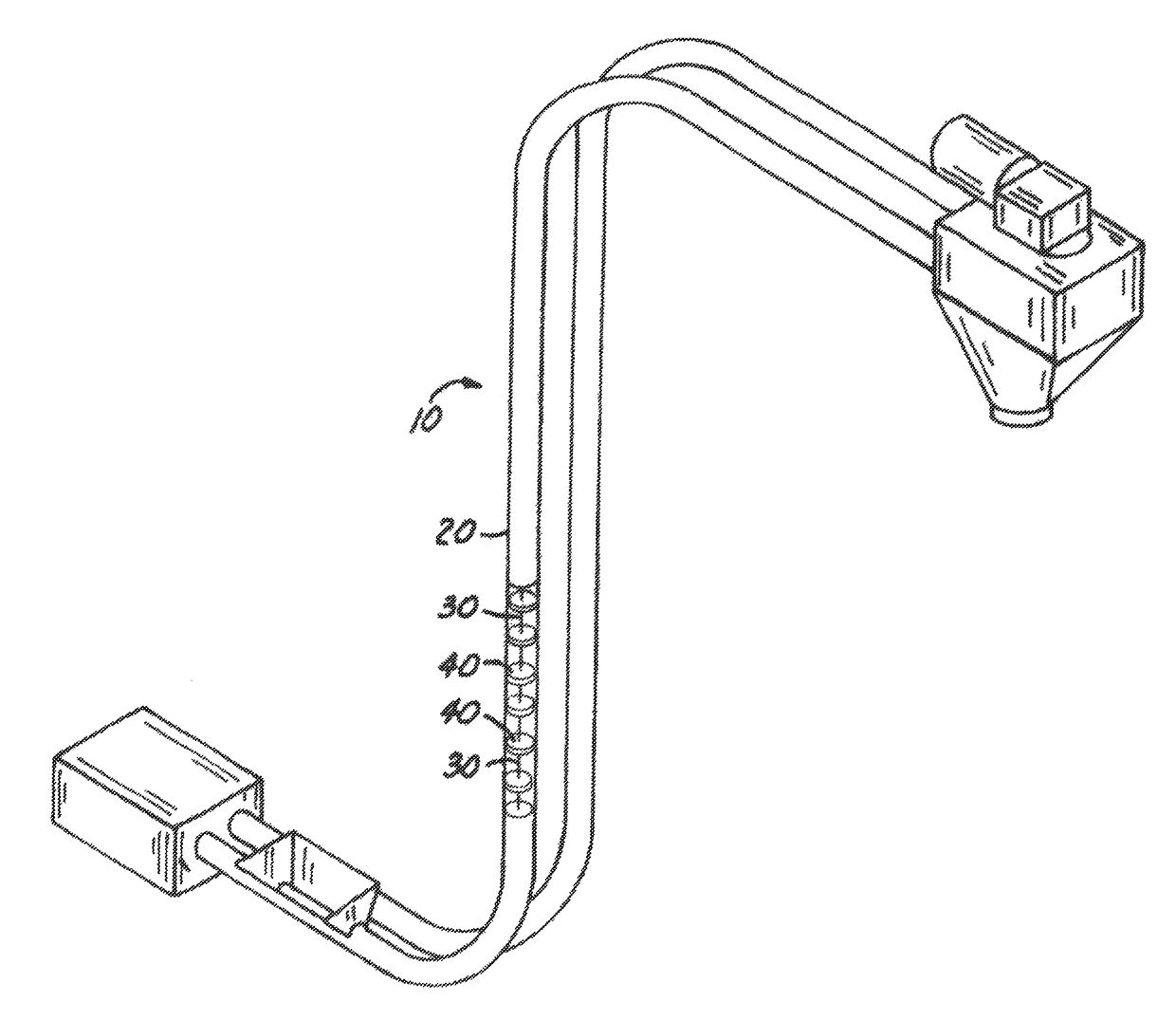
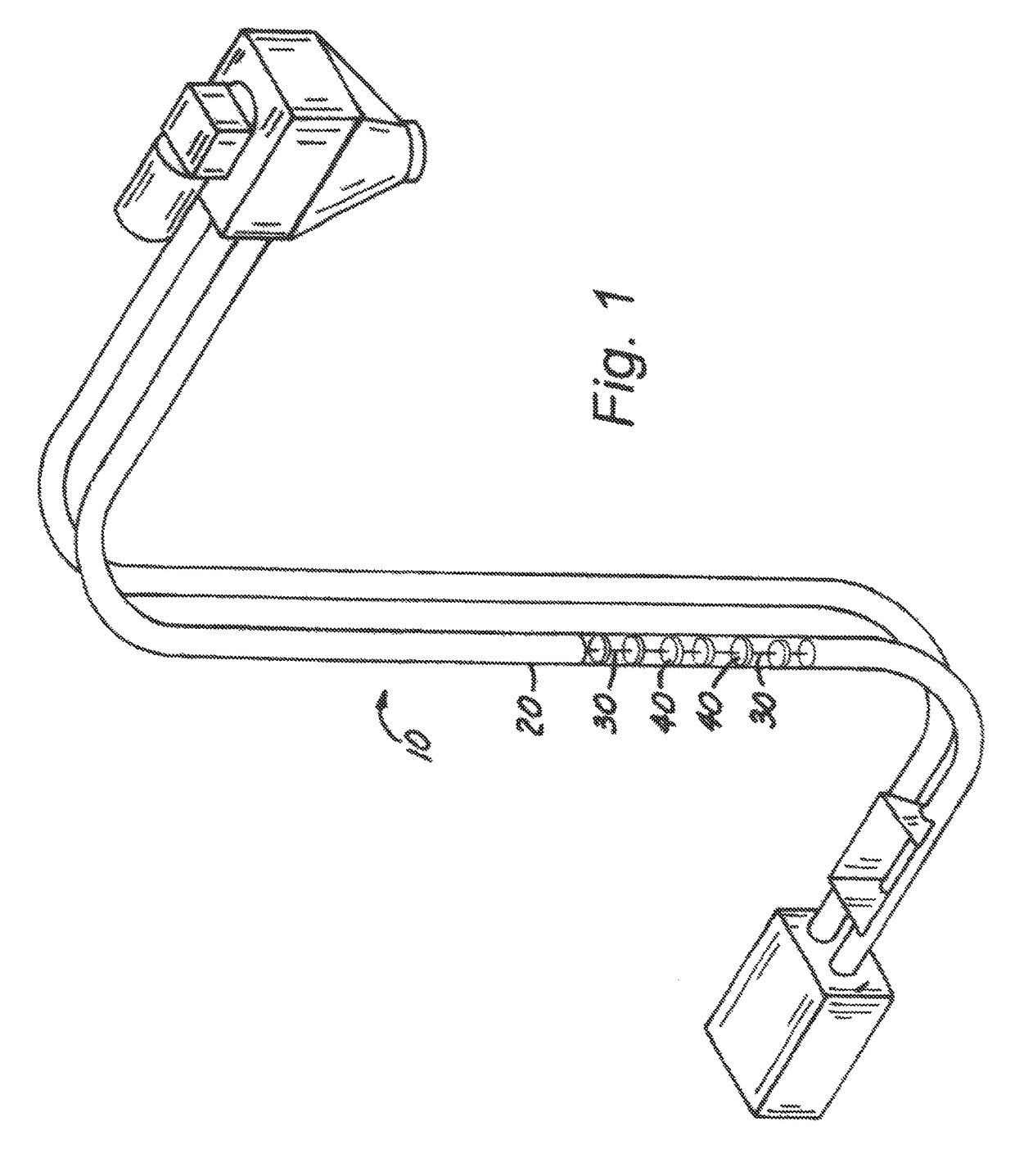
[0029]As can be seen by reference to the drawings, and in particularly to FIG. 1, the cable conveyor system that forms the basis of the present invention is designated generally by the reference number 10. The conveyor system 10 includes a tube 20, a cable 30 that moves within the interior of the tube 20, and a number of discs 40 spaced at intervals along the cable 30.

[0030]The tube 20 has an exterior wall 22, an interior wall 24, and an interior cavity 26 through which the cable 30 travels.

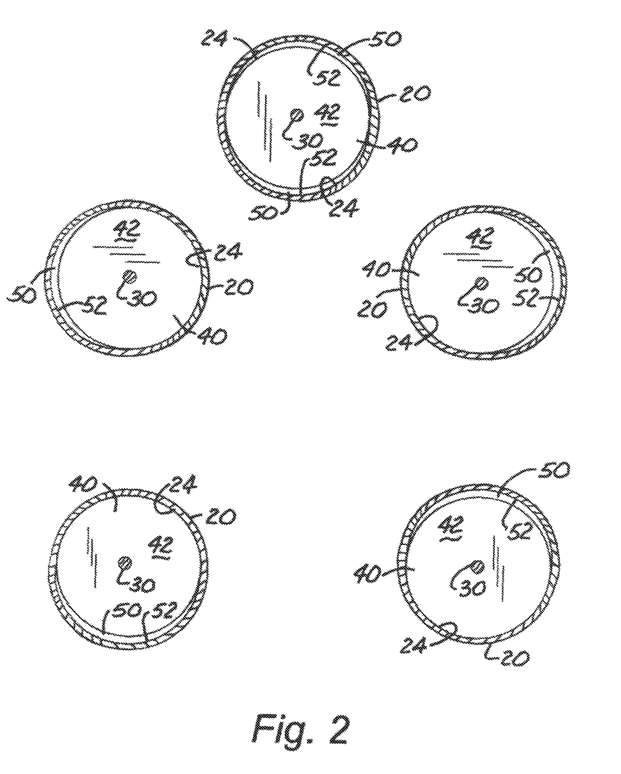
[0031]The disc 40 of the present invention has a body member 42 having a central portion 44 attached to the cable 30, and a peripheral edge 46 that has and annular groove 48 formed therein.

[0032]The term “disc”, for the purposes of this document, is defined as any attachment on an endless loop tubular system which is larger than the cables, chains, etc. to which they are attached for the purpose of pushing material to be conveyed through the system. These “discs” are commonly circular at the oute...


PUM


Abstract

A close tolerance disc for a flexible member conveyor including a disc body member and a movable resilient ring. The ring is preferably formed of a durable polymer interlocking ring where the ring outer periphery closely matches the inside surface of the conveyor tubing. The resilience of the ring biases it to conform to the inside surface of the conveyor tubing to provide 100% conveyance of the material in the system. The ring can move in place within a groove in the body member of the disc, as well as distort to self-align and conform to the irregularities that are present in the manufacturing of the conveyor tubular components. The ring is easily removeable for quick replacement and cleaning. The interlocking ends of the ring keep the ring ends in place and in line to prevent the ends from being misaligned while passing through a partially cutaway portion of the tube.

Description

BACKGROUND OF THE INVENTION[0001]Field of the Invention[0002]The present invention relates to the field of cable conveyors, and more particularly to the discs that are attached to the cable travelling through a tubular circuit.[0003]Description of the Related Art[0004]As can be seen by reference to the following U.S. Pat. Nos. 3,905,473, 4,071,136, 4,395,973 and 7,267,218, (all hereby incorporated herein by reference in their entirety), the prior art is replete with myriad and diverse cable conveyor systems.[0005]Cable conveyor systems have long been in use to transport materials from a charging location to discharging locations along the path of the conveyor. Discs attached at intervals to the cable, or other flexible member, travel within the tube to contact and move the material through the tube to desired locations within a facility.[0006]The systems can, for example, wind through a building to have outlets wherever the user may wish to deliver the product being conveyed. There ...

Claims


Application Information

Patent Timeline
IPC IPC(8): B65G19/22B65G19/14B65G19/20
CPCB65G19/22B65G19/14B65G19/24
Inventor NICHOLSON, ERIC L.
Owner INTRACO
Learn More