Housing for a rotary vane pump

a technology of rotary vane pump and housing, which is applied in the direction of mechanical equipment, rotary or oscillating piston engines, liquid fuel engines, etc., can solve the problem of limited lubrication on the drive, and achieve the effect of reliable positioning of the housing

Inactive Publication Date: 2017-08-29
PFEIFFER VACUUM GMBH
View PDF16 Cites 4 Cited by
  • Summary
  • Abstract
  • Description
  • Claims
  • Application Information

AI Technical Summary

Benefits of technology

[0010]The evacuation chamber adjoins the suction side. In this chamber, a smaller pressure prevails then on the discharge side of the pump. Because the compression is greater on the discharge side, a noticeably higher temperature prevails on the discharge side than on the suction side. In order to prevent tensions and deformations that would exist in the housing because of temperature gradients, the inventive housing is provided with a greater number of cooling ribs in the region of the housing in which a greater compression takes place, then in the region of the housing in which a smaller compression of the to-be-pumped medium takes place. Because of the uniform cooling of the housing, hardly any tension or deformations occur in the housing. Thereby, the displacement of bearing locations which takes place upon occurring of large deformation, is prevented.
[0045]The inventive housing for a rotary vane pump permits to optimize power consumption, efficiency, vacuum characteristics, reliability and service-friendliness. In addition, the inventive embodiments enable to form a compact housing, with regard to its outer dimensions, and which can be easily used, permit to reduce manufacturing costs, and allow an operation with both horizontal and vertical delivery.

Problems solved by technology

Lubrication is limited to the drive space separated from the compression chamber by a sealing element.

Method used


Image

  • Housing for a rotary vane pump
  • Housing for a rotary vane pump
  • Housing for a rotary vane pump

Examples


Embodiment Construction

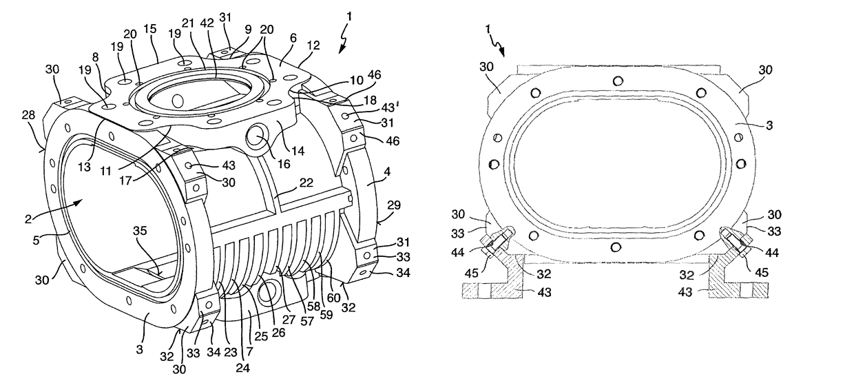
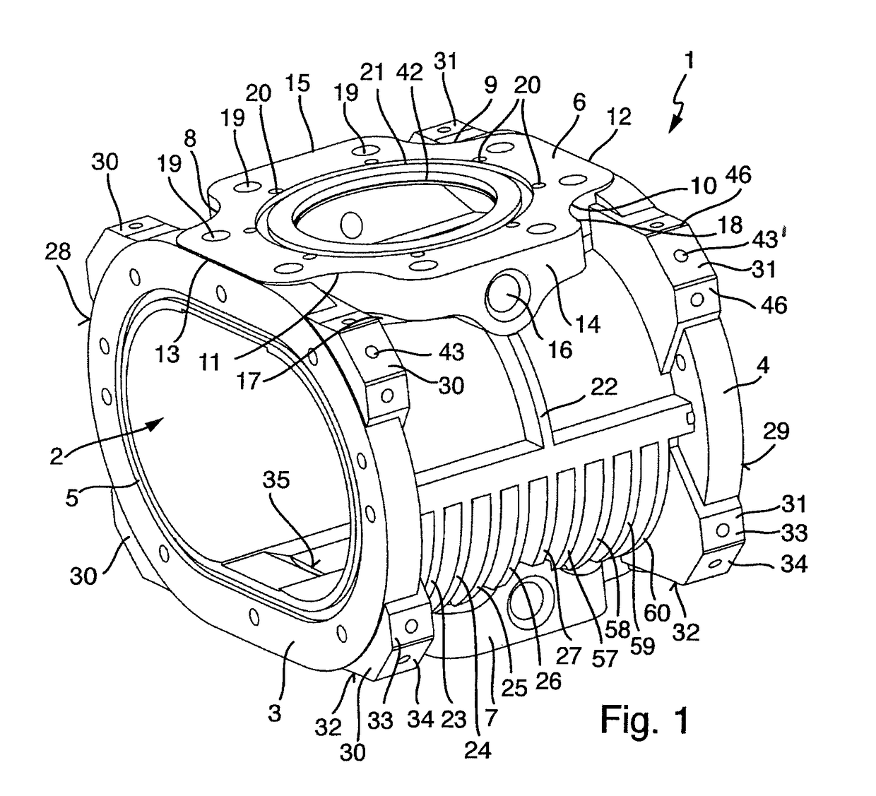
[0058]FIG. 1 shows a housing 1 of a rotary vane pump. In the compression chamber 2, there are arranged two, not shown, rotors synchronously rotatable, in a non-contact manner, in opposite directions. The rotors have a shape of “8” and are separated from each other and from respective stators by a gap.

[0059]The housing 1 is shown in FIG. 1. The flanges 3 and 4 are equipped during an operation with covers 52, 53, as shown in FIG. 9, and which tightly abut the flanges 3 and 4. In addition, as shown in FIG. 1, the flange 3 is provided with a groove 5 for receiving a seal. As shown in FIG. 9, shafts 54, 55 for rotors extend through the covers 52, 53.

[0060]According to FIG. 1, the housing 1 has a suction flange 6 and a discharge flange 7. The suction flange 6 has a square basic surface in corner regions of which, recesses 8, 9, 10, 11 in form of notches extending into the basic surface of the flange 6 are provided. Sides 12, 13 of the flange 6 extend parallel to each other, can be aligned...


PUM


Abstract

A housing for a rotary vane pump includes a suction flange and a discharge flange having a multi-angular cross-section with at least two sides extending parallel to each other, cooling ribs provided on an outer surface of the housing, with the number of cooling ribs in the region with a high internal pressure being greater than a number of cooling ribs in the region with a low internal pressure, inlet and outlet, with the inlet cross-section being greater than the outlet cross-section, and connection elements provided on the housing and each having two installation surfaces connected by a connection surface.

Description

BACKGROUND OF THE INVENTION[0001]1. Field of the Invention[0002]The present invention relates to a housing for a rotary vane pump having a suction flange and a discharge flange.[0003]2. Description of the Prior Art[0004]Rotary vane pumps are well known. In a rotary vane pump, two rotors synchronously rotate in a housing in opposite directions, without contacting each other. The rotors can have a shape of 8 and are separated from each other and from the stator by a narrow gap. The forwarded gas is transmitted from the suction opening to the discharge opening.[0005]A shaft is driven by a motor. The synchronization of the other shaft is carried out with a tooth gear pair located in the drive space. Lubrication is limited to the drive space separated from the compression chamber by a sealing element.[0006]Because no friction takes place in the compression chamber, the rotary vane pump can be operated with a high speed up to 7,500 revolution / min. The symmetrical mass distribution of the ...

Claims


Application Information

Patent Timeline
Patent Type & Authority Patents(United States)
IPC IPC(8): F03C4/00F04C2/00F04C15/00F04C2/344F04C29/04F04C29/12F04C18/12F01C21/10F04C18/344
CPCF04C15/0096F01C21/10F04C2/344F04C18/126F04C18/344F04C29/04F04C29/12F04C2240/30F04C2250/101F04C2250/102
Inventor KOBUS, CHRISTOPHERSCHNEIDER, KEVIN
Owner PFEIFFER VACUUM GMBH
Why Eureka
Try Eureka