Pipe laying machine and pipe laying method

a technology of pipelayer and pipe laying method, which is applied in the direction of pipe laying and repair, soil shifting machine/dredger, pipe/joint/fitting, etc., can solve the problems of generating the maximum overturning moment, high cost of both purchase or rental of a large number of machines, and the load bearing capacity of these pipelayers is greater, so as to reduce the number of machines employed, the effect of easy operation and control

Inactive Publication Date: 2017-08-29
LAURINI OFF MEC
View PDF21 Cites 2 Cited by
  • Summary
  • Abstract
  • Description
  • Claims
  • Application Information

AI Technical Summary

Benefits of technology

[0021]More in detail, an object of the present invention is to provide a pipe laying machine that can be loaded to a greater extent with respect to a prior art machine, without the risk of overturning or of sustaining other accidents.
[0022]Another object of the present invention is to produce a pipe laying machine that is simple to manage and control during the laying operation.
[0023]A further object of the present invention is to produce a pipe laying machine that can easily operate on tracks, at the side of trenches, of limited width.
[0024]Yet another object of the present invention is to propose a method for laying pipes that allows, with equal loads, a decrease in the number of machines employed with respect to prior art laying methods.
[0025]One more object of the present invention is to propose a method for laying pipes that allows a decrease in the laying time, and consequently in the costs of the work.
[0026]Finally, an object of the present invention is to increase the safety in the construction site by reducing handling of suspended loads.

Problems solved by technology

One of the main problems affecting machines of this type is related to the risk of overturning during the laying step when the pipe, which can weigh hundreds of tons, is in the position farthest from the center of gravity of the machine, generating the maximum overturning moment.
This implies high costs both for the purchase or rental of a large number of machines, and for the use of a higher number of operators to drive them.
The load bearing capacity of these pipelayers, although greater due to the presence of the counterweights, is nonetheless limited and dependent on the overall dimensions of the machine that, due to problems linked to transport, generally cannot exceed given values.
For these reasons, in order to reduce the number of machines used, and consequently the costs of the work, the machines are often deliberately used beyond their load limits, thus increasing the risk of accidents caused by overturning.
Moreover, pipe laying operations performed with this system have other problems.
Therefore, lifting and laying operations must be performed with particularly slow movements, which affect the times required to complete the work.
Another limit of prior art pipe laying machines and of the related laying method, consists in the fact of having to move very large suspended loads in the vicinity of workers on the ground, who are required to direct and control correct positioning of the pipe in the trench.
Finally, these prior art machines require considerable space on the track at the edge of the trench both in order to pick up the pipe from the ground and for normal travel.

Method used


Image

  • Pipe laying machine and pipe laying method
  • Pipe laying machine and pipe laying method
  • Pipe laying machine and pipe laying method

Examples


Embodiment Construction

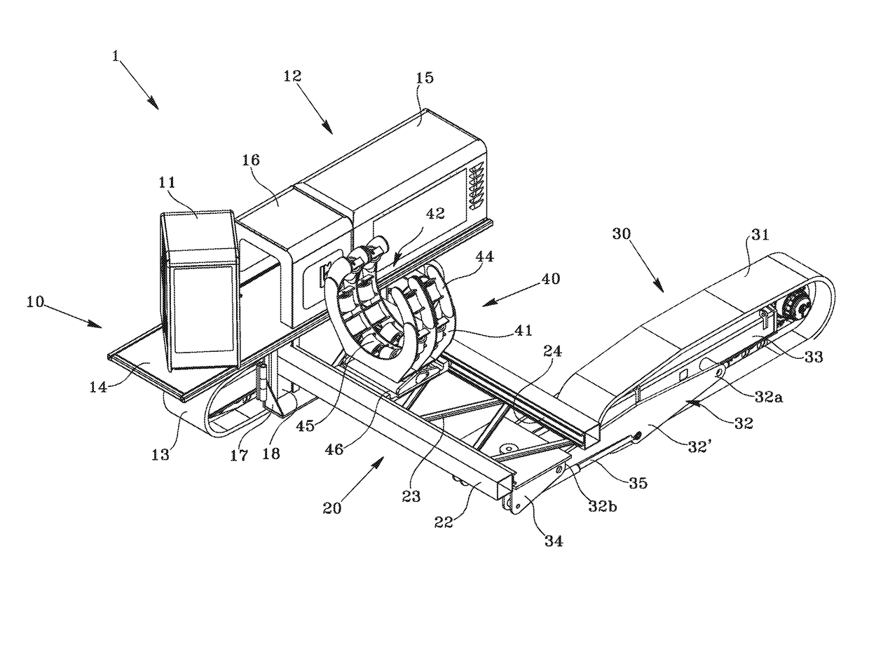
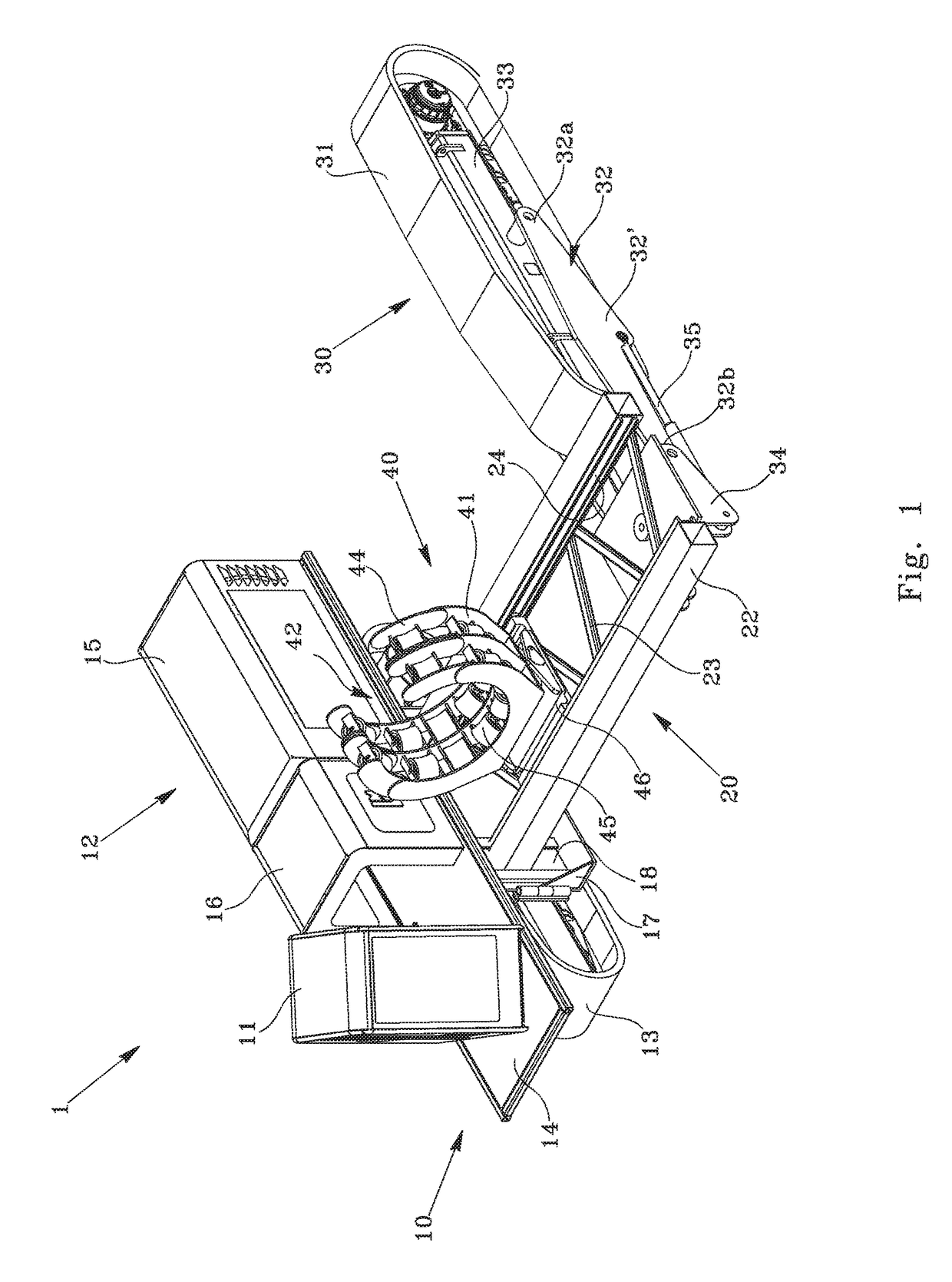
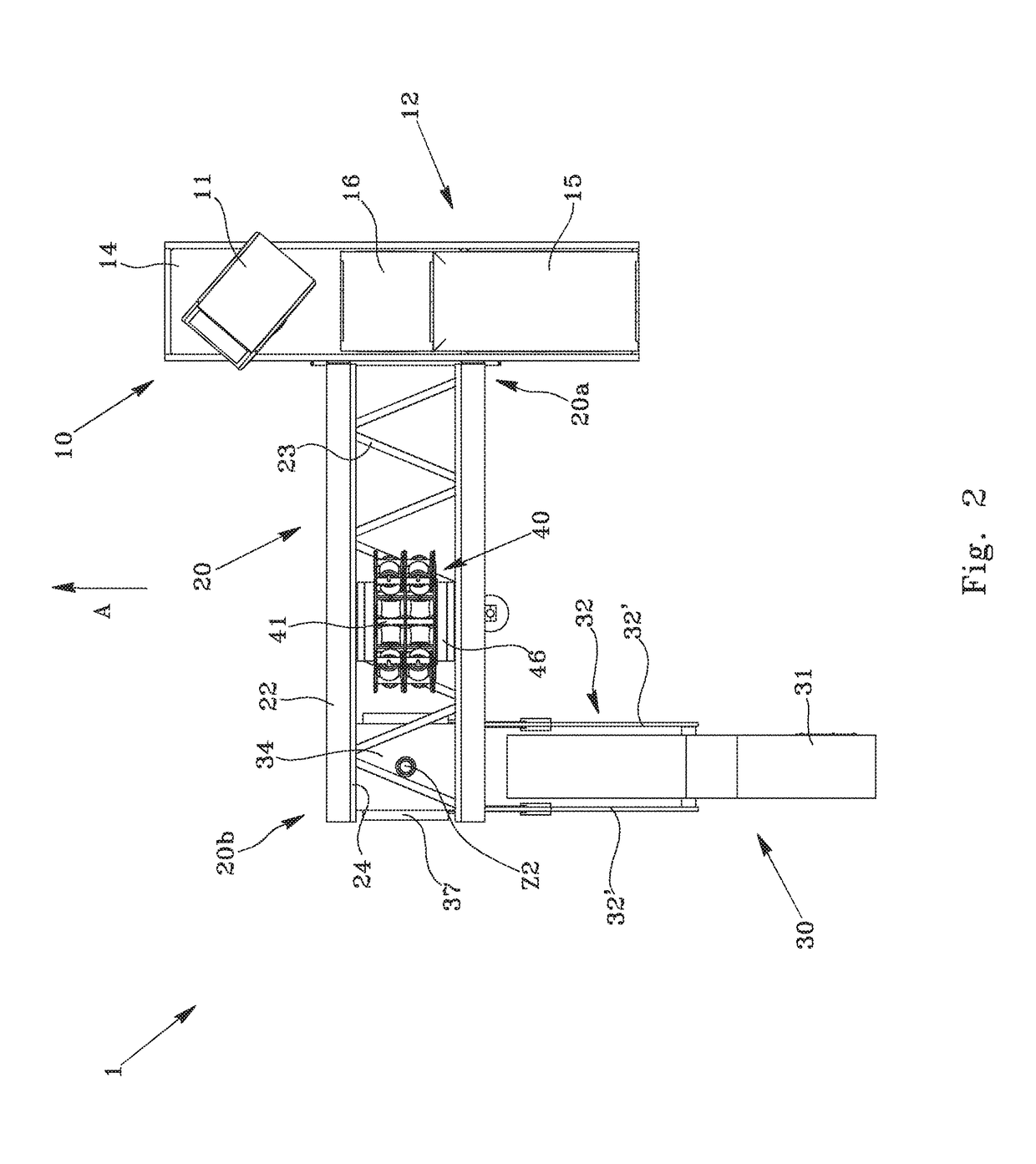
[0059]With reference to the accompanying figures, the pipe laying machine 1 comprises a self-propelled chassis, indicated as a whole with 10, on which a driver's cab 11 is installed. Said self-propelled chassis 10 is moved in a direction of forward movement A by a powertrain 12, preferably by means of at least one continuous track 13 or, alternatively, by means of wheels or other rolling means suitable for rough ground and / or with reduced adhesion (soil, mud, etc.).

[0060]According to a preferred aspect of the invention, the driver's cab 11 and the powertrain 12 are mounted on a platform 14, in turn supported by said continuous track 13. The driver's cab 11 is preferably connected to said platform 14 by means of a fifth wheel (not visible in the figure) that allows a rotation about a vertical axis so that the operator can face the direction of forward movement A and the trench in which the pipe is laid.

[0061]According to the invention, the powertrain 12 can include an endothermic eng...


PUM


Abstract

A pipe laying machine for laying a pipe in a trench, includes a first self-propelled chassis (10) on which a driver's cab (11) and powertrain (12) are located, a beam (20) connected at a first end (20a) to the chassis and which extends laterally therefrom, a second moving chassis (30) connected at a second end (20b) of the beam and a guiding and supporting element (40) of a pipe, sliding on the beam toward and away from the self-propelled chassis, in which the self-propelled chassis can travel on a track (P) at the edge of the trench, the moving chassis (30) can travel on the bottom of the trench, and the guiding and supporting element can translate to carry the pipe to the trench so that by moving the machine forward along a direction of forward movement the cantilevered portion of pipe is laid on the bottom of the trench.

Description

BACKGROUND OF THE INVENTION[0001]Field of the Invention[0002]The present invention relates to a pipe laying machine and to the related method for laying pipes in a trench.[0003]The invention relates to the field of machinery used to lay medium or large pipes such as oil pipelines, gas pipelines or the like.[0004]Typically, these pipes are assembled directly at the laying site, by welding different tubular sections arranged aligned with one another at the edge of a trench. After being assembled, a stretch of pipe of a given length (tens or hundreds of meters) is buried by placing it on the bottom of a trench, which will then be covered with backfill.[0005]To handle the various sections of pipe, and to lay this pipe in the trench, machines known as pipe laying machines are generally used.[0006]Description of the Related Art[0007]Known pipe laying machines generally comprise a continuous track mounted frame, to which there is applied laterally a boom (or crane) that enables lifting and...

Claims


Application Information

Patent Timeline
Patent Type & Authority Patents(United States)
IPC IPC(8): F16L1/036F16L1/032E02F5/10
CPCF16L1/036E02F5/10F16L1/032F16L1/065F16L55/00
Inventor LAURINI, MARCO
Owner LAURINI OFF MEC
Why Eureka
Try Eureka