Method and apparatus for converting thermal energy to mechanical energy

a technology of mechanical energy and thermal energy, applied in the field of engines, can solve the problems of engine failure to reach the full potential within a reasonable cost and package, engine efficiency is limited all current widespread use technologies are limited in efficiency to approximately less than 40%, etc., to achieve simple thermal management, improve efficiency, and improve efficiency

Inactive Publication Date: 2007-10-23
CROW DARBY
View PDF21 Cites 39 Cited by
  • Summary
  • Abstract
  • Description
  • Claims
  • Application Information

AI Technical Summary

Benefits of technology

[0013]Against the foregoing background, the present invention was developed. Several objects and advantages of the present invention are: (1) to provide a method and apparatus for implementing a new and unique thermodynamic cycle for converting thermal energy to mechanical energy; (2) to provide an engine that can use a wide range of fuels; (3) to provide an engine that performs with a higher efficiency than is achieved with present technology; (4) to provide for power conversion in an engine which operates quietly; (5) to provide an engine design in which the sealing required is the same as in standard engine designs in current use; (6) to provide for an engine with more effective regeneration by eliminating the Stirling regenerator and replacing it with a method of regeneration in the form of isentropic compression and expansion; (7) to eliminate the need for cooling apparatus of any kind; (8) to provide for an engine in which there is only one heat exchange process required of the apparatus; (9) to provide for an engine with simpler thermal management than the Stirling engines; and (10) to provide for a method and apparatus whereby the effective cold temperature of the engine is lower than that achievable in known Ericsson or Stirling engines.
[0014]Further objects an advantages of the present invention are: (11) to provide for an engine such that very large thermal gradients across critical components need not be maintained; (12) to provide for an engine in which temperatures required of components is not significantly greater than that already achieved by standard automotive materials; (13) to provide for an apparatus whereby the dead space in the engine is smaller than standard Stirling engines; and (14) to provide an engine that achieves the above objects and advantages in a package that is small and inexpensive to build.
[0015]There is provided in accordance with the present invention a method and apparatus for converting thermal energy to mechanical energy using a unique thermodynamic cycle permitting the use of a wide range of fuels and operating at a higher efficiency than is with present art in a package that is reasonably small and inexpensive to build.

Problems solved by technology

Unfortunately, all technologies currently in widespread use are limited in efficiency to approximately less than 40% and are constrained in the type of fuel that can be used.
While such engines in theory are capable of remarkably high efficiencies, in practice the engines have failed to reach their full potential within a reasonable cost and package.
There are several reasons why Carnot, Stirling and Ericsson cycle engines have not been proven effective or broadly commercialized.
Most important is the difficulty in achieving the heat transfer required during the isothermal heat transfer processes to reach a reasonable power output within a reasonable cost and package.
Because the Stirling and Ericsson engines are closed cycles that are typically under significant pressure, problems with design and sealing abound in containing the working fluid during operation.
The stringent sealing requirements of these engines tend to increase mechanical friction.
The effectiveness of the regenerator or “recuperator” used in these engines is limited.
Nonetheless, an effectiveness of 75% results in a significant loss of thermal energy and efficiency.
However, increasing the temperature differences effectively causes the working fluid hot temperature to drop and the cold temperature to increase, thereby decreasing efficiency.
Moreover, the critical components in Ericsson and Stirling engines, such as valves, cylinders and pistons, are subject to extremely high temperatures.
Because exhaust or waste heat in Ericsson and Stirling engines is typically rejected through the heat exchanger during the cold isothermal heat transfer process, the cooling capabilities required to maintain the heat exchanger temperature are prohibitive.
The difficulties in thermally isolating each exchanger and preventing the heat from the hot exchanger from being transferred to the other two, and thus wasted, are well known.
Additionally because they use three heat exchangers (hot, cold and regenerator), Stirling engines have excessive dead space that reduces specific power and efficiency.

Method used


Image

  • Method and apparatus for converting thermal energy to mechanical energy
  • Method and apparatus for converting thermal energy to mechanical energy
  • Method and apparatus for converting thermal energy to mechanical energy

Examples


Embodiment Construction

)

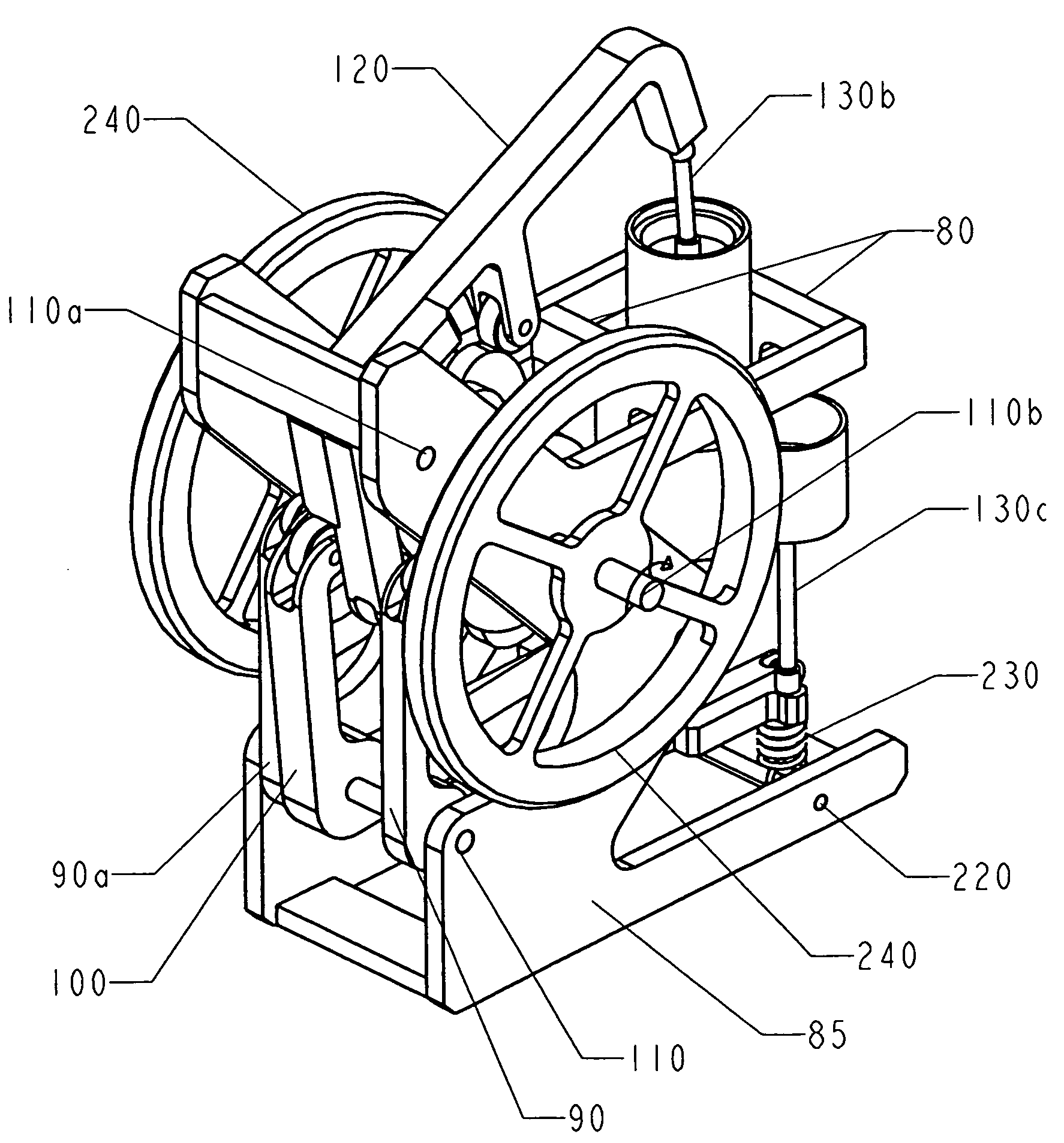
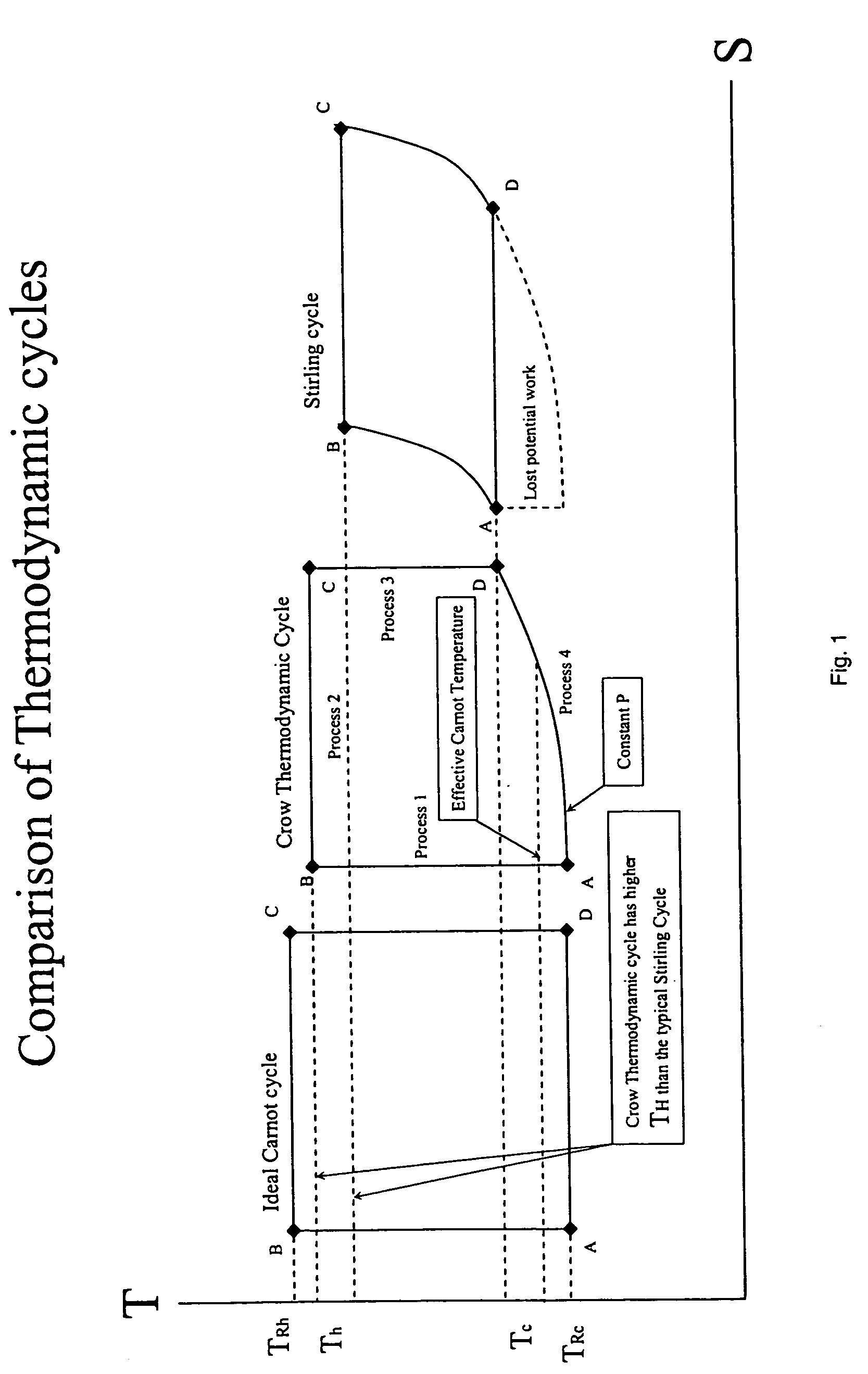
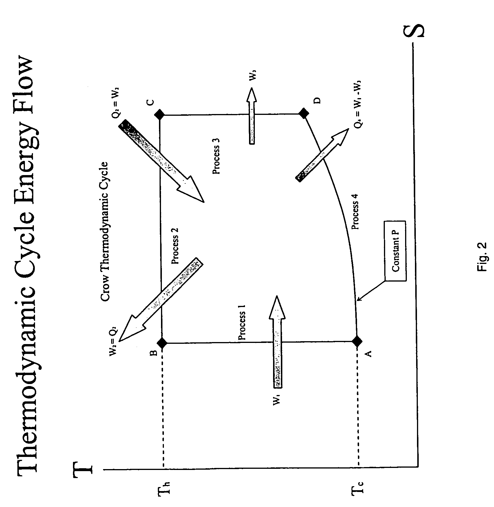
[0049]The present invention relates to an innovative apparatus and method for converting thermal energy into mechanical energy. Reference is made to a thermodynamic cycle that will sometimes be called the “Crow Thermodynamic Cycle,” the “Crow Cycle” or “the subject cycle.” Also in the course of this disclosure reference will be made to a number of mathematical variables. For convenience, the several variables and their meanings are set forth in Table 1.

[0050]

TABLE 1List of VariablesηThermodynamic efficiency, as measured by total work divided by thermal heatηidealThermodynamic efficiency, assuming the working fluid reaches reservoirTcLow temperature reached by the working fluid during the thermodynamic cycleThHigh temperature reached by the working fluid during the thermodynamic cycleTRcCold reservoir temperatureTRhHot reservoir temperatureTc,eEffective isothermal low temperature reached by the working fluidTh,eEffective isothermal high temperature reached by the working fluidTATemp...


PUM


Abstract

A method and apparatus for converting thermal energy to mechanical energy which can use a wide range of fuels and perform with a high efficiency. Operating on a little utilized thermodynamic cycle of isentropic compression, isothermal expansion, isentropic expansion and finally constant pressure cooling and contraction. The external heat engine utilizes a heat exchanger carrying heat from the external energy source to the working parts of the engine. Pistons and cylinders are activated by appropriate means to adiabatically compress the working fluid, for example ambient air, to transfer the entire mass of the air through the heat exchanger to accomplish isothermal expansion followed by adiabatic expansion and, finally, exhaust the air to ambient to allow for constant pressure cooling and contraction. Valve pistons in conjunction with the cylinders form valves that allow for the exchange of working fluid with ambient. Energy is added to the engine during isothermal expansion, whereby the energy of compression is added by a flywheel or other appropriate energy storage means, said flywheel stores energy recovered during adiabatic expansion. The thermodynamic cycle described and the engine embodiments disclosed, when run in reverse, perform as a heat pump or refrigeration device.

Description

BACKGROUND OF THE INVENTION[0001]1. Field of the Invention (Technical Field):[0002]The present invention relates to engines, specifically to an engine utilizing an improved method for using external heat to heat a unit mass of working fluid and thereby convert the thermal energy to mechanical energy, where the unit mass is later expelled and a new unit mass of working fluid is introduced to repeat the cycle.[0003]2. Background Art[0004]The conversion of chemical and thermal energy to useful mechanical and electrical energy has been studied for hundreds of years. This interest has led to some engines widely used today that accomplish this feat, well-known examples being the internal combustion engines, and gas combustion- and steam-driven turbines. Unfortunately, all technologies currently in widespread use are limited in efficiency to approximately less than 40% and are constrained in the type of fuel that can be used.[0005]One group of engines for converting energy known variously ...

Claims


Application Information

Patent Timeline
Patent Type & Authority Patents(United States)
IPC IPC(8): F01B29/10
CPCF02G1/043F28D21/00F28D17/02F02G2242/44F02G2244/12
Inventor CROW, DARBY
Owner CROW DARBY
Why Eureka
Try Eureka