Apparatus and methods for using fiber optic arrays in optical communication systems

Inactive Publication Date: 2005-03-10
OPTICAL COMM PRODS
View PDF16 Cites 36 Cited by
  • Summary
  • Abstract
  • Description
  • Claims
  • Application Information

AI Technical Summary

Benefits of technology

[0008] In another disclosed embodiment, parallel fiber optic connectors may be employed in combination with vertical-cavity surface-emitting lasers (“VCSELs”) to provide multiple signal-independent optical communication paths in a high density single mode configuration that offers smaller size and reduced power consumption at a lower cost than traditional SFF-based implementations. Using VCSELs enables multiple optical transmitters to be integrated into a single transmit module to which a parallel fiber optic connector, such as an MTP™ connector, may be coupled to provide an independent optical transmitter for each fiber optic port of an MTP connector array. In such an implementation, two or more 1310 nm-based transmit and receive array modules (e.g., based on 1310 nm VCSEL technology) may be coupled together, for example, using MTP™ connectors in conjunction with industry standard single and/or duplex fiber connectors. When compared to conventional 1310 nm SFF-based transceivers, such an implementation may be used to realize system-level improvements such as increased system level densities, reduced power supplies, elimination of cooling fans, lower system costs, smaller system footprint for remote and/or space-restricted locations (e.g., remotely located pedestals, distribution cabinets in a multi-tenant unit or corporate campus, elevated installations on utility poles, etc.), increased battery b

Problems solved by technology

At the same time that service providers are attempting to deploy such higher bandwidth solutions, they face market constraints that increasingly make such solutions more difficult to implement, e.g., reduced capital budgets, physical space limitations, HVAC (heating, ventilation, and air conditioning) limitations, increasing power costs due to limited power grid capacity, etc.
However, despite the implementation of 1310 nm-based optical technologies, ser

Method used


Image

  • Apparatus and methods for using fiber optic arrays in optical communication systems
  • Apparatus and methods for using fiber optic arrays in optical communication systems
  • Apparatus and methods for using fiber optic arrays in optical communication systems

Examples


Embodiment Construction

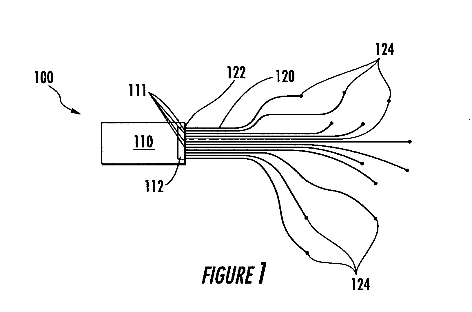
[0024]FIG. 1 illustrates one embodiment of a fiber optic communication assembly 100 that includes an optical communication module 110 having multiple fiber optic ports 111 configured as an array 112. Multiple fiber optic conductors 120 are shown optically coupled to each of the fiber optic ports 111 of array 112. In this regard, a fiber optic conductor may be any combination of structure (e.g., fiber, filament, rod, etc.) and material (e.g., glass, plastic, etc.) suitable for conducting light waves from point to point. Although illustrated as a single segment in FIG. 1, each of fiber optic conductors 120 may include one or more individual fiber optic segments, optical connectors and / or other optical coupling devices coupled between its respective first end 122 and second end 124.

[0025] As shown in FIG. 1, multiple fiber optic conductors 120 extend from array 112 in adjacent parallel relationship (i.e., extending from array 112 in parallel or substantially parallel manner), and then...


PUM


Abstract

Systems and methods for optical communication that may be employed to couple together fiber optic arrays of two or more optical communication modules using parallel fiber optic connectors and physically distinct and signal-independent optical communication paths. The disclosed systems and methods may be employed to provide separate signal-independent communication paths having signal transport characteristics that meet standards required for single fiber single point-to-single point applications.

Description

CROSS-REFERENCE TO RELATED APPLICATIONS [0001] This application is a continuation of and claims priority from earlier filed U.S. patent application Ser. No. 10 / 087,648, filed Mar. 1, 2002.BACKGROUND OF THE INVENTION [0002] The present invention relates generally to optical communications, and more particularly to fiber optic communication systems. [0003] Optical communication technologies are employed in a wide variety of communication environments. Examples of such communication environments include, but are not limited to, telecommunications, networking, data communications, industrial communication links, medical communications links, etc. In networking environments, fiber optics have traditionally been employed in the network core as long-haul backbones. More recently, fiber optic technologies have been implemented at the network edge, e.g., in metropolitan area network (“MAN”) and local area network (“LAN”) environments. Examples of other environments in which optical communica...

Claims


Application Information

Patent Timeline
IPC IPC(8): G02BG02B6/28G02B6/36G02B6/44
CPCG02B6/4246G02B6/4472G02B6/4452
Inventor MAYER, ROBERT C.
Owner OPTICAL COMM PRODS
Why Eureka
Try Eureka