
Muzzle flash simulator and method for an imitation machine gun

a simulator and imitation machine gun technology, applied in the field of imitation machine gun muzzle flash simulator and simulator, can solve the problems of high cost of ammunition alone, difficult and expensive training of soldiers and military defense personnel in the effective use of high-powered rapid-fire machine guns, and high difficulty in implementing effective use of high-powered rapid-fire machines, etc., to achieve effective simulation of muzzle flash, high intensity, high intensity

Active Publication Date: 2017-08-29
PATHFINDER SYST
View PDF13 Cites 9 Cited by
  • Summary
  • Abstract
  • Description
  • Claims
  • Application Information

AI Technical Summary

Benefits of technology

The present invention relates to a device that can simulate the muzzle flash of an actual machine gun in a training program. This device uses a small light source that fits within the muzzle of an imitation machine gun and creates a high intensity burst of light that is comparable to an actual muzzle flash. The device is designed to allow users to acclimate to the sensation of firing an actual machine gun, particularly when using night vision goggles. The device is turned on and off quickly to avoid a sensation different from firing an actual machine gun. The invention can reliably use the components without premature or unexpected failure, making it effective for training purposes.

Problems solved by technology

In modern circumstances, it is difficult and expensive to train soldiers and military defense personnel in the effective use of high-powered rapid-fire machine guns, by simply allowing such individuals to practice using the actual guns with live ammunition.
The ammunition rounds are expensive, for example costing up to five dollars per round.
The cost of ammunition alone quickly multiplies when it is recognized that a typical machine gun is capable of firing hundreds of rounds per minute.
Adequate space for a practice gunnery range may not be readily available.
Significant costs are involved in transporting the personnel and the equipment to suitable remote locations where adequate gunnery practice can be performed.
It is difficult to instruct during a live ammunition training session due to the noise and safety considerations involved when others are involved in similar, close-by, live-ammunition practice activities.
Furthermore, it may be difficult to vary the targets quickly at a live-ammunition gunnery range.
These problems and practical constraints are exacerbated when training individuals to shoot from a moving vehicle such as a helicopter.
As a result, live gun practice requires considerable space, and the cost of operating the helicopter greatly multiplies the overall training cost.
Because of the familiarity gained from training with the imitation machine gun, use of the imitation machine gun should be essentially the same as the use of the actual machine gun; otherwise, differences in functionality or performance create unexpected problems or difficulties when using the actual machine gun.
However, duplicating the burst of light from a muzzle flash has proven somewhat problematic.
While light sources in the environment surrounding the imitation machine gun can be controlled to deliver momentary flashes of light, the light does not create the intensity and sensual effect as occurs with an actual machine gun when sighting along the barrel.
The operator may become disoriented or at least distracted if the operator has not become accustomed to the momentary blanking effects in the night vision goggles.
Delivering momentary flashes of light from light sources in the environment surrounding the imitation machine gun is not as effective in blanking the night vision goggles as when the burst of light is emitted from the muzzle of the actual machine gun.
While the high intensity light can be delivered from a variety of light sources, those light sources may be so large physically that they must be attached separately to the barrel.
Extra components connected to the imitation machine gun can cause a lack of familiarity or awkwardness in the use of the actual machine gun.
Extra components may create an expectation of a certain feel, appearance and operating style that are not present when using the actual machine gun, and those differences may lead to degraded performance of the user in actual circumstances.
Light sources using filaments have a tendency for residual light emission from the heated filament after the pulse of energy has terminated.

Method used


Image

  • Muzzle flash simulator and method for an imitation machine gun
  • Muzzle flash simulator and method for an imitation machine gun
  • Muzzle flash simulator and method for an imitation machine gun

Examples


Embodiment Construction

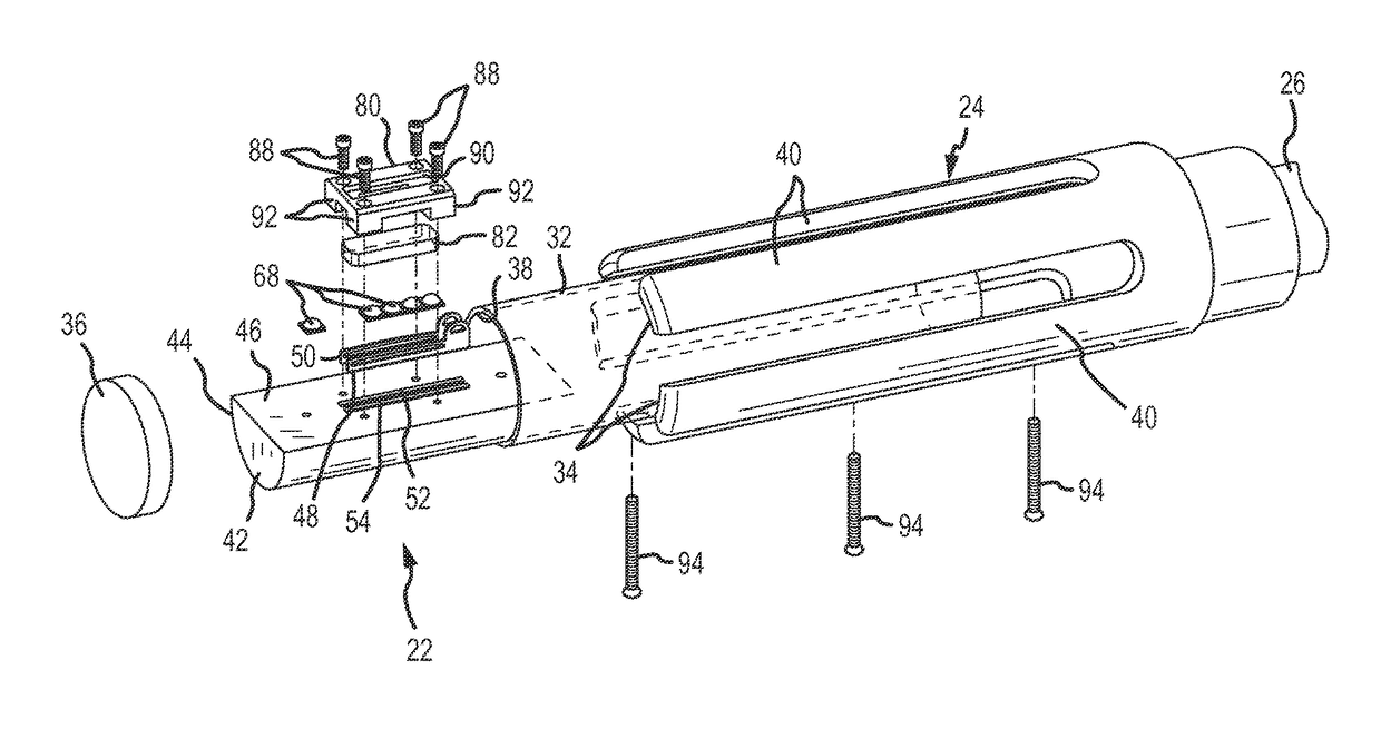
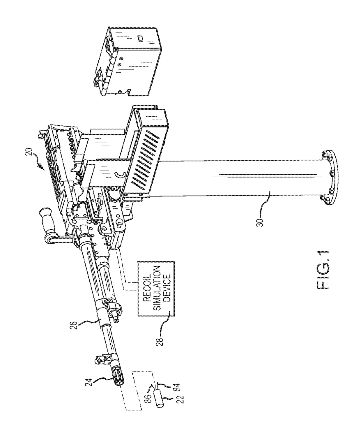
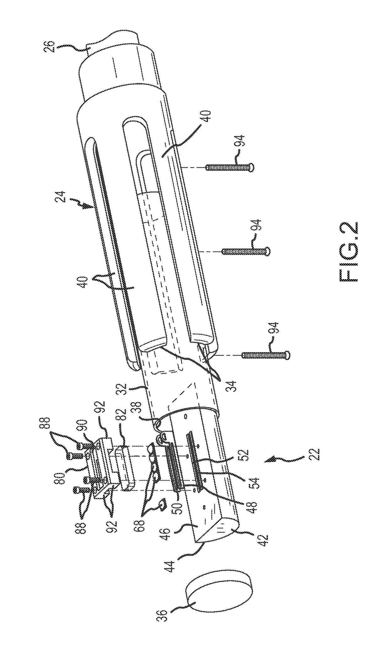
[0026]An exemplary imitation machine gun 20 which is used in simulated weapons training activities is shown in FIG. 1. The machine gun 20 duplicates the look and feel and the mechanical features of an actual machine gun which it imitates. The machine gun 20 includes a muzzle flash simulator 22 (FIGS. 2-4), which fits within a flash suppressor 24 located on a distal or muzzle end of a barrel 26 of the imitation machine gun 20. The muzzle flash simulator 22 emits bursts of high-intensity light which emulates each flash of light created by firing an actual ammunition round from an actual machine gun.

[0027]The muzzle flash simulator 22 is concealed within the flash suppressor 24 (FIG. 4). The flash suppressor 24 is used in an actual machine gun to dissipate the compressed gas and burst of light created by the exploded gunpowder from firing an actual ammunition round. Since there is no such explosion when firing the imitation machine gun 20, the muzzle flash simulator 22 emulates the bur...


PUM


Abstract

A muzzle flash from firing a live ammunition round from an actual machine gun is stimulated in an imitation machine gun by locating a LED light source within a flash suppressor attached to a muzzle end of a barrel of the imitation machine gun. When energized, the light source emits a burst of light through vents in the flash suppressor. A plurality of LEDs create the burst of light.

Description

CROSS REFERENCE TO RELATED APPLICATION[0001]This invention is related to an invention for a Recoil Simulator and Method for an Imitation Machine Gun, described in U.S. patent application Ser. No. 14 / 541,515, filed concurrently herewith, and assigned to the assignee of the present invention. The subject matter of this prior application is incorporated herein fully by this reference.FIELD OF THE INVENTION[0002]This invention relates generally to training persons to operate an actual machine gun by using an imitation or simulated machine gun. More particularly, the present invention relates to a new and improved muzzle flash simulator and method which simulates, in the imitation machine gun, the flash of light from the muzzle created by firing actual ammunition rounds from an actual machine gun.BACKGROUND OF THE INVENTION[0003]In modern circumstances, it is difficult and expensive to train soldiers and military defense personnel in the effective use of high-powered rapid-fire machine g...

Claims


Application Information

Patent Timeline
Patent Type & Authority Patents(United States)
IPC IPC(8): F41A33/02
CPCF41A33/02
Inventor LOWRANCE, KYLECOHLMIA, C. ROSS
Owner PATHFINDER SYST
Learn More