Signal calculator
a calculator and signal technology, applied in the field of signal calculators, can solve the problems of reducing the accuracy of calculated results, and achieve the effect of decreasing the influence of signal calculation results
- Summary
- Abstract
- Description
- Claims
- Application Information
AI Technical Summary
Benefits of technology
Problems solved by technology
Method used
Image

Examples
first embodiment
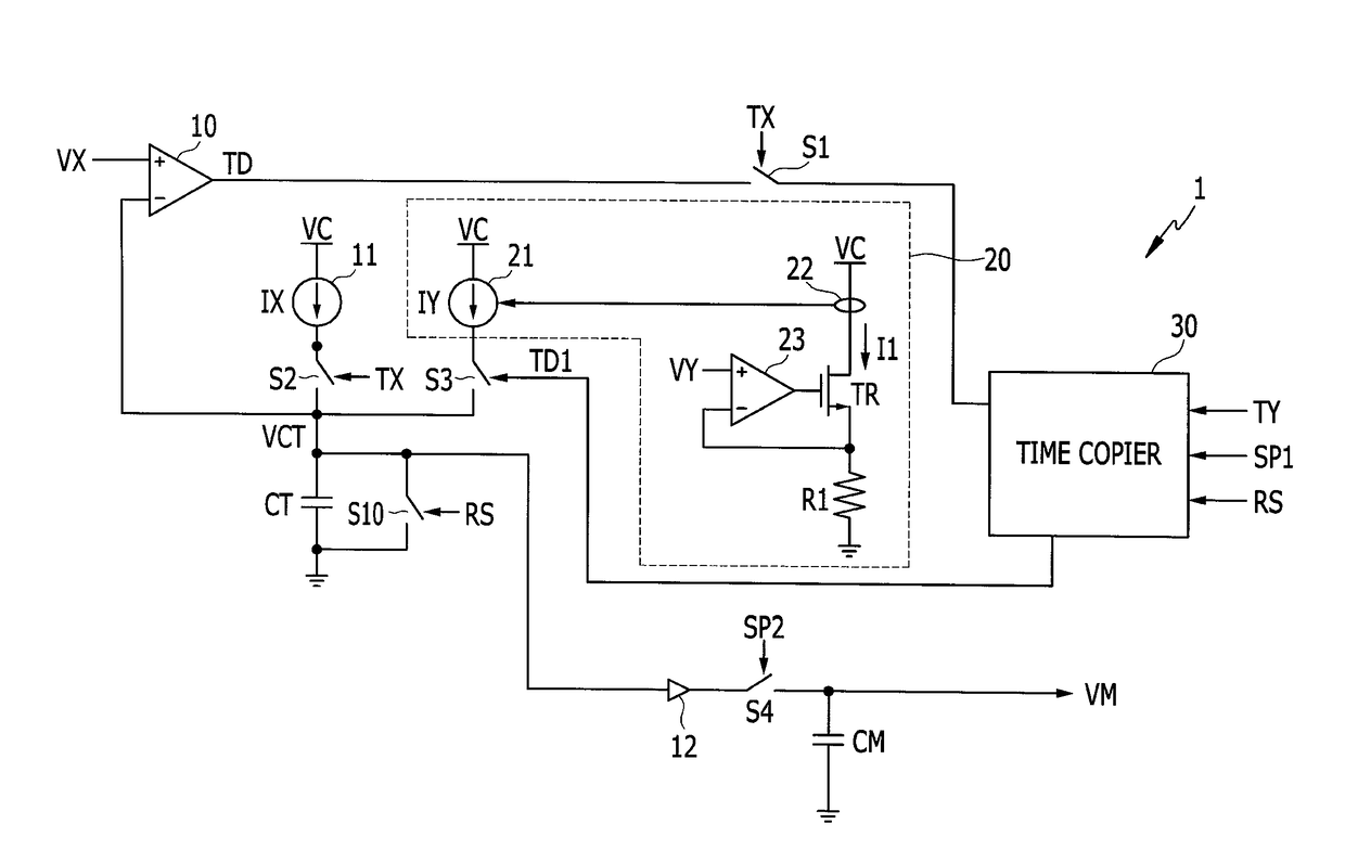
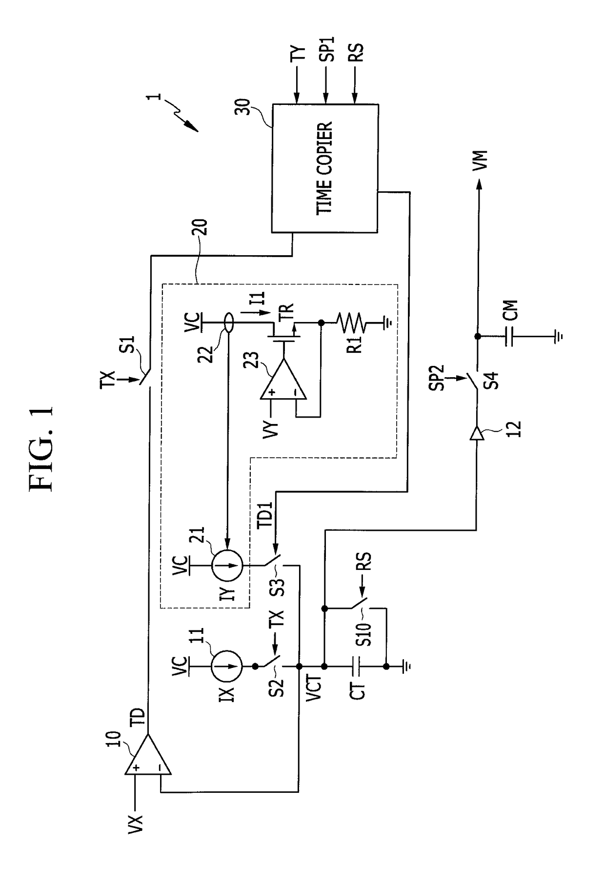
[0050]FIG. 1 is a view illustrating a voltage multiplier according to a
[0051]As illustrated in FIG. 1, a voltage multiplier 1 receives a voltage VX and a voltage VY and generates a voltage VM according to the product of the two voltages. The voltage multiplier 1 according to the embodiment generates and copies time information corresponding to any one of the two voltages VX and VY and generates the voltage VM based on the copied time information and a current corresponding to the other one of the two voltages VX and VY. The embodiment illustrated in FIG. 1 generates and copies a signal TD based on time information corresponding to the voltage VX and generates the voltage VM based on a copied signal TD1 and a current IY corresponding to the voltage VY.
[0052]First, the voltage multiplier 1 charges a capacitor CT with a current IX of a current source 11 during a first period according to a signal TX to increase a voltage VCT. The current source 11 uses a voltage VC to generate the curr...
second embodiment
[0093]Hereinafter, a time copier will be described with reference to FIG. 4.
[0094]FIG. 4 is a view illustrating the time copier according to the second embodiment.
[0095]Like reference numerals will be used for like elements compared to the first embodiment described above, and detailed descriptions thereof will be omitted.
[0096]Compared to the first embodiment, a time copier 40 of the second embodiment uses the resistance R1 instead of the current source 31. The resistance R1 is connected between a voltage VCC and the switch S6 and the switch S7.
[0097]The capacitor CT1 is charged by the voltage VCC during the period in which the switch S6 is turned on by the signal TD and the period in which the switch S7 is turned on by the signal TY. The voltage VCT1 may increase by a time constant determined by the resistance R1 and the capacitor CT.
[0098]Although a voltage multiplier has been described as an example of an analog signal calculator so far, the present disclosure is not limited th...
third embodiment
[0099]FIG. 5 is a view illustrating a time divider according to a
[0100]As illustrated in FIG. 5, a time divider 3 samples a voltage VA and a voltage VB respectively corresponding to a signal TA and a signal TB which represent a first time and a second time, and generates a signal TVD based on a result of comparing voltages which are increased by slopes on the basis of the voltage VB and the voltage VA.
[0101]A current source 51 uses the voltage VC to generate a current IB, and the switch S10 is connected between the current source 51 and one end of a capacitor CT2. A current source 52 uses the voltage VC to generate a current IA, and a switch S11 is connected between the current source 52 and the one end of the capacitor CT2. A switch SW1 is connected in parallel to both ends of the capacitor CT2.
[0102]The switch S10 performs a switching operation according to the signal TB, the switch S11 performs a switching operation according to the signal TA, and the switch SW1 performs a switch...
PUM
 Abstract
Description
Claims
Application Information
 - R&D
- Intellectual Property
- Life Sciences
- Materials
- Tech Scout
- Unparalleled Data Quality
- Higher Quality Content
- 60% Fewer Hallucinations
Browse by: Latest US Patents, China's latest patents, Technical Efficacy Thesaurus, Application Domain, Technology Topic, Popular Technical Reports.
© 2025 PatSnap. All rights reserved.Legal|Privacy policy|Modern Slavery Act Transparency Statement|Sitemap|About US| Contact US: help@patsnap.com