
Hardware-oriented dynamically adaptive disparity estimation algorithm and its real-time hardware

a dynamically adaptive, disparity estimation and hardware technology, applied in image analysis, image enhancement, processor architecture/configuration, etc., can solve the problems of difficult real-time processing of disparity estimation, easy selection of wrong disparity results, and mismatches in textureless regions, so as to improve algorithm performance and improve algorithm performance. , the effect of improving the accuracy of selection

Active Publication Date: 2017-09-05
ECOLE POLYTECHNIQUE FEDERALE DE LAUSANNE (EPFL)
View PDF38 Cites 1 Cited by
  • Summary
  • Abstract
  • Description
  • Claims
  • Application Information

AI Technical Summary

Benefits of technology

The proposed AWDE algorithm is a hybrid solution that combines the strengths of the Census Transform and the BW-SAD methods. It improves the efficiency of the algorithm for hardware implementation. The algorithm uses adaptive window sizes based on texture features on the image and provides dynamic and static configurability to have satisfactory disparity estimation quality for images with different contents. The device includes SAD and BW-SAD computations for the sampled pixels in the searched block and Hamming computations for all pixels. Overall, the proposed technology reduces computational complexity and improves the accuracy of uniting pixels in an image with different modes.

Problems solved by technology

The computational complexity of disparity estimation algorithms and the need of large size and bandwidth for the external and internal memory make the real-time processing of disparity estimation challenging, especially for High Resolution (HR) images.
Although the low-complexity Census method can determine the disparity of the pixels where the image has a texture, mismatches are observed in textureless regions.
Moreover, due to a 1-bit representation of neighboring pixels, the Census easily selects wrong disparity results.
However [26] does not present hardware implementation of the adaptive window selection, and it does not benefit from the adaptive combination of Census and BW-SAD methods.
The hardware presented in [25] is not able to dynamically change the window size, since it requires to re-synthesize the hardware for using different window sizes.
In addition, the hardware presented in [25] does not benefit from the Census cost metric.

Method used


Image

  • Hardware-oriented dynamically adaptive disparity estimation algorithm and its real-time hardware
  • Hardware-oriented dynamically adaptive disparity estimation algorithm and its real-time hardware
  • Hardware-oriented dynamically adaptive disparity estimation algorithm and its real-time hardware

Examples


Embodiment Construction

[0065]The main focus of the AWDE algorithm is its compatibility with real-time hardware implementation while providing high-quality DE results for HR. The algorithm is designed to be efficiently parallelized to require minimal on-chip memory size and external memory bandwidth.

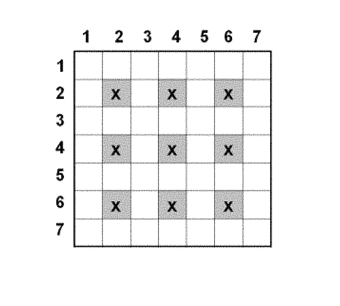
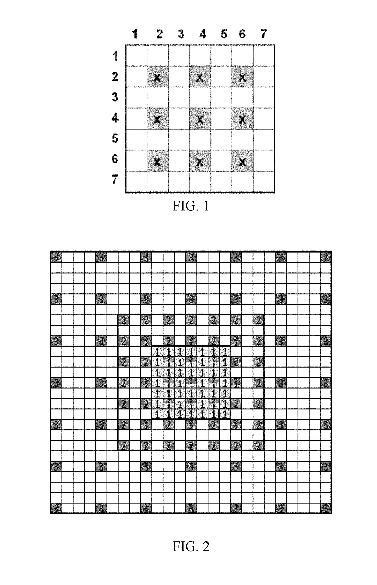
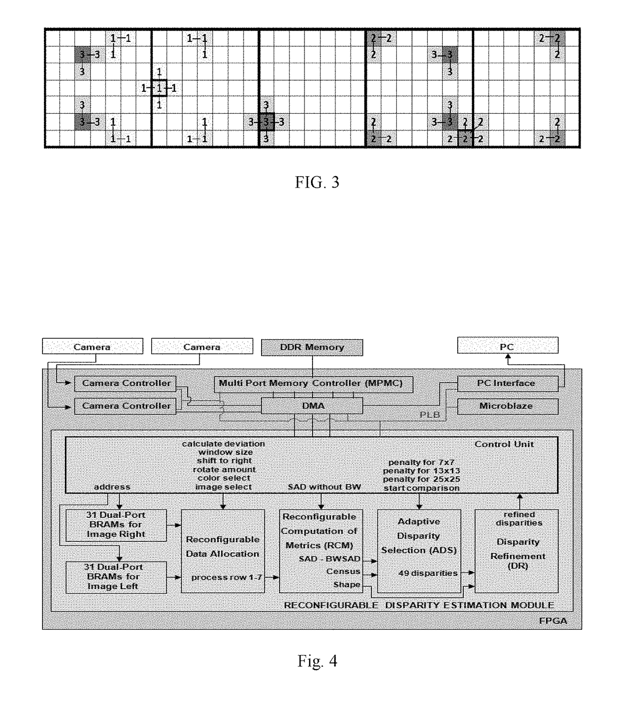
[0066]As a terminology, we use the term “block” to define the 49 pixels in the left image that are processed in parallel. The term “window” is used to define the 49 sampled neighboring pixels of any pixel in the right or left images with variable sizes of 7×7, 13×13 or 25×25. The pixels in the window are used to calculate the Census and BW-SAD cost metrics during the search process.

[0067]The algorithm consists of three main parts: window size determination, disparity voting, and disparity refinement. The parameters that are used in the AWDE algorithm are given in Table 1.

[0068]The window size of the 49 pixels in each block is adaptively determined according to the Mean Absolute Deviation (MAD) of the pixel in t...


PUM


Abstract

A real-time stereo camera disparity estimation device comprises input means arranged to input measured data corresponding to rows of left and right images; a plurality of on-chip memories arranged to buffer the input measured data; a vertical rotator hardware module configured to align the rows of left and right images in a same column; a reconfigurable data allocation hardware module; a reconfigurable computation of metrics hardware module; and an adaptive disparity selection hardware module configured to select disparity values with the minimum matching costs.

Description

BACKGROUND OF THE INVENTION[0001]Depth estimation is an algorithmic step in a variety of applications such as autonomous navigation, robot and driving systems [1], 3D geographic information systems [2], object detection and tracking [3], medical imaging [4], computer games and advanced graphic applications [5], 3D holography [6], 3D television [7], multiview coding for stereoscopic video compression [8], and disparity-based rendering [9]. These applications require high accuracy and speed performances for depth estimation.[0002]Depth estimation can be performed by exploiting three main techniques: time-of-flight (TOF) camera, LIDAR sensor and stereo camera. A TOF camera easily measures the distance between the object and camera using a sensor, circumventing the need of intricate digital image processing hardware [10]. However, it does not provide efficient results when the distance between the object and camera is high. Moreover, the resolution of TOF cameras is usually very low (20...

Claims


Application Information

Patent Timeline
Patent Type & Authority Patents(United States)
IPC IPC(8): H04N13/02G06T19/20G06T1/20G06T7/00H04N13/00H04N13/128
CPCH04N13/0239G06T1/20G06T7/97H04N13/0207G06T2207/10012G06T2207/10021H04N2013/0081H04N13/207H04N13/239H04N13/128
Inventor AKIN, ABDULKADIRLEBLEBICI, YUSUFSCHMID, ALEXANDREBAZ, IPEKBOYBAT, IREMATAKAN, HUSEYIN BARIS
Owner ECOLE POLYTECHNIQUE FEDERALE DE LAUSANNE (EPFL)
Learn More