
Apparatus and method for collaborative adaptation of hierarchically-designed schematics to variant design requirements

Active Publication Date: 2017-09-12
CADENCE DESIGN SYST INC
View PDF6 Cites 4 Cited by
  • Summary
  • Abstract
  • Description
  • Claims
  • Application Information

AI Technical Summary

Benefits of technology

The patent describes a system and method that allows for easy sharing of design data among different teams and projects. It also allows for efficient merging of data from different projects. Overall, the system improves design collaboration and efficiency.

Problems solved by technology

However, the advantage of this collaboration becomes a disadvantage when variants are also employed.
More importantly, if an individual element in the design is changed after variants are prepared, those variants may become inapplicable, forcing the system-level designer to start over.

Method used


Image

  • Apparatus and method for collaborative adaptation of hierarchically-designed schematics to variant design requirements
  • Apparatus and method for collaborative adaptation of hierarchically-designed schematics to variant design requirements
  • Apparatus and method for collaborative adaptation of hierarchically-designed schematics to variant design requirements

Examples


Embodiment Construction

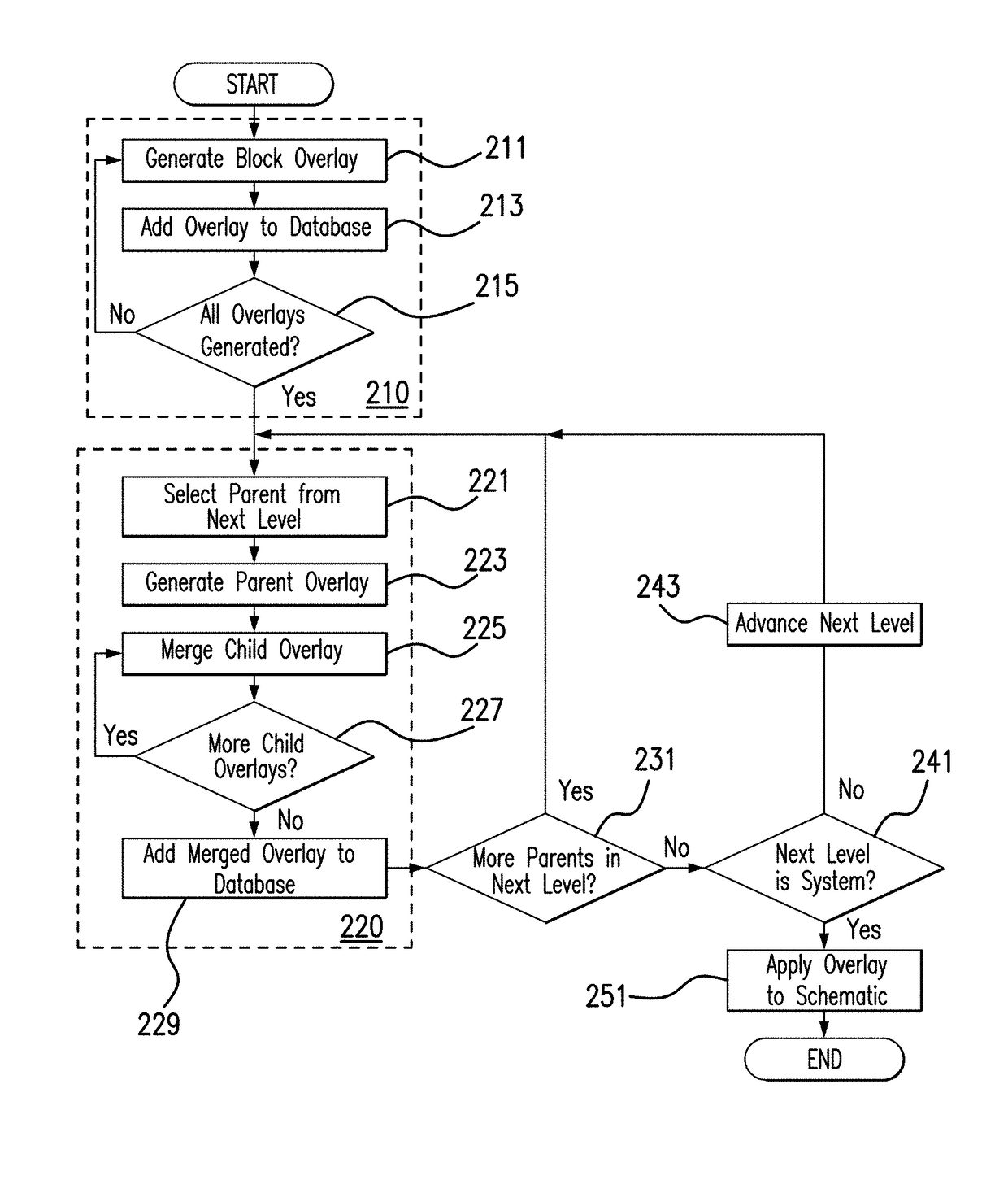
[0035]Reference will now be made in detail to exemplary embodiments, which are illustrated in the accompanying drawings, wherein like reference numerals refer to the like elements throughout. The embodiments are described below in order to explain the disclosed system and method by referring to the figures.

[0036]Section headings are included in this Detailed Description. It is noted that these section headings are for convenience only and should not be interpreted as limiting the scope of the claimed invention in any way.

[0037]Generally, an electronic system or device may be designed by way of a schematic. In an electronic design context, a schematic is typically supported by one or more data files defining the design of the desired system, which may be generated, amended, and interpreted by electronic design software tools. Information defined in the schematic may include components, interconnections therebetween, and parameters of both such as part numbers, specific locations, siz...


PUM


Abstract

A planned schematic for an electronic system is hierarchically divided into base-level schematic blocks which may be designed individually. In accordance with a plurality of sets of design requirements, variant overlays are designed for each base-level schematic block, each overlay including variant parameter values which may replace corresponding parameter values of the schematic blocks. The schematic blocks are integrated to generate a system-level schematic, and the variant overlays for a given set of design requirements are merged to generate a system variant overlay. Parameter values of the system variant overlay may then replace corresponding parameter values of the system-level schematic to generate a variant schematic for the given set of design requirements. Using this system and methodology, variant designs may be collaboratively generated by multiple designers each with expertise in particular schematic blocks and / or variant requirements, and may be shared either at the system level or at lower levels.

Description

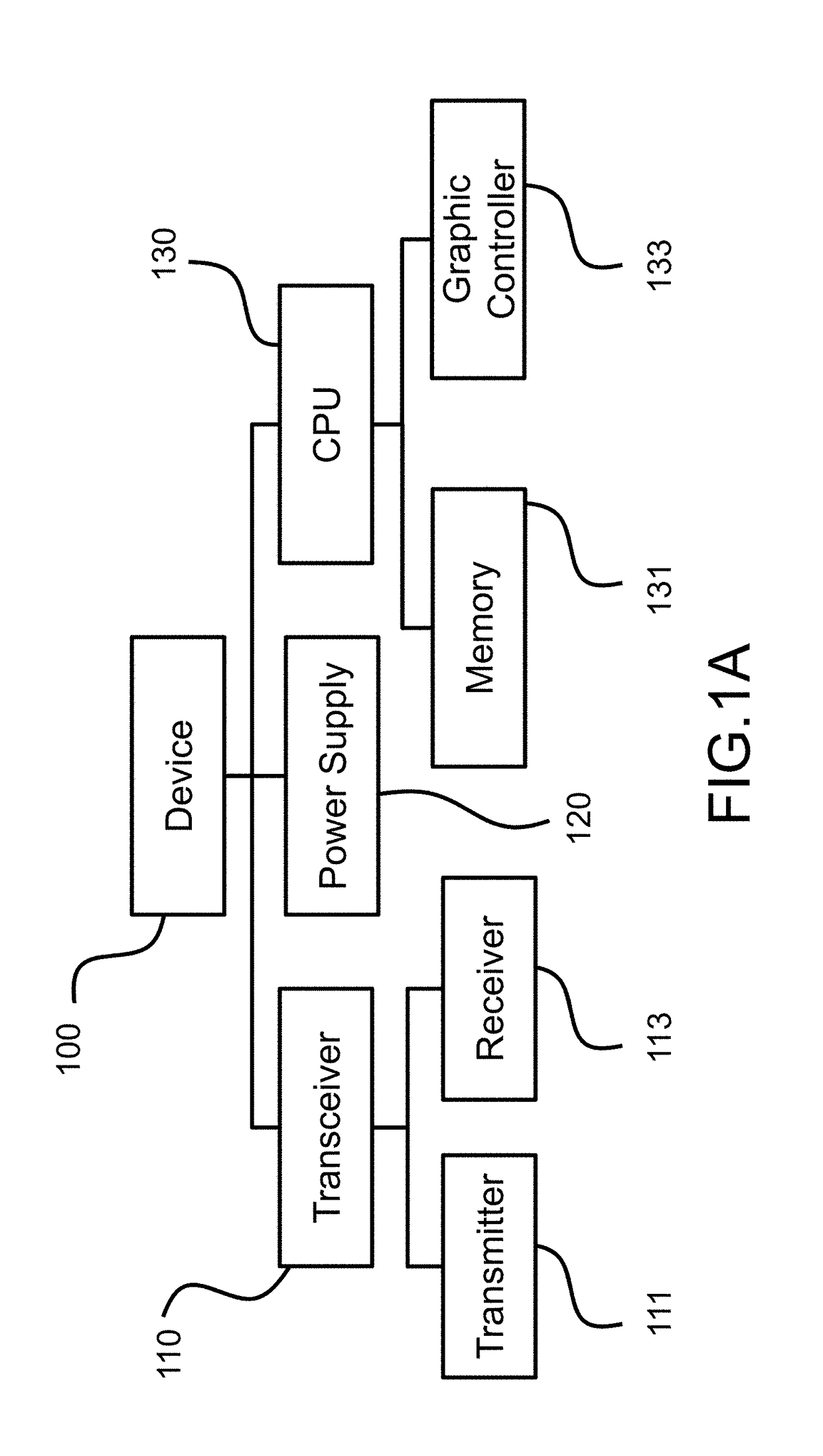
BACKGROUND OF THE INVENTION[0001]The subject system and method are generally directed to adapting electronic schematics to differing design requirements.[0002]An electronic system or device may be intended for use under multiple design requirements which require small changes to certain design parameters. For instance, a device operating on a standard power supply may need to be adapted for different voltages depending on the country or region of use, or a controller for a vehicle may have a slightly different operation depending on the specific vehicle model and options. In these cases, the necessary changes may be sufficiently minor that it is more efficient to alter the original design for the device into a “variant” system design (or, simply, a “system variant”), rather than starting over.[0003]A design project may be divided into smaller, “lower-level” elements. For example, a smartphone design may be divided into the CPU, memory, power supply, and so forth. These elements may ...

Claims


Application Information

Patent Timeline
IPC IPC(8): G06F17/50H05K3/00
CPCG06F17/5045H05K3/0005G06F2217/74G06F30/30G06F2111/12
Inventor GANDOTRA, SHILPACHANDRA, ADITYAGOEL, GUNJANSINGH, INDERPALGUPTA, NIKHILJAIN, ISHANI
Owner CADENCE DESIGN SYST INC
Learn More