Suspension board with circuit and method of manufacturing the same

a suspension board and circuit technology, applied in the direction of printed circuit manufacturing, printed circuit aspects, support for heads, etc., can solve the problems of reducing the reliability of the suspension board with a circuit, deficiency such as a short circuit of the wiring, and possible short circuit between, so as to improve thermal dissipation at the projection, prevent short circuit, and prevent short circuit.

Active Publication Date: 2017-09-12
NITTO DENKO CORP
View PDF20 Cites 2 Cited by
  • Summary
  • Abstract
  • Description
  • Claims
  • Application Information

AI Technical Summary

Benefits of technology

[0007]In this manner, if the wetting and spreading of the molten solder to an unintended portion occurs in the suspension board with a circuit at which the connection terminals are formed at the both surfaces of the insulating layer, a deficiency such as a short circuit of the wiring is likely to occur. As a result, reliability of the suspension board with a circuit is reduced.
[0030](12) The projection may be formed of metal. In this case, the thermal dissipation at the projection is improved. Thus, the wetting and spreading of the molten solder can be blocked by the simple configuration.

Problems solved by technology

In a case in which the element is connected to the connection terminal at the lower surface of the insulating layer using solder, however, a short circuit is likely to occur between the adjacent connection terminals at the lower surface of the insulating layer, or between the connection terminals at both surfaces of the insulating layer due to wetting and spreading of molten solder.
In this manner, if the wetting and spreading of the molten solder to an unintended portion occurs in the suspension board with a circuit at which the connection terminals are formed at the both surfaces of the insulating layer, a deficiency such as a short circuit of the wiring is likely to occur.
As a result, reliability of the suspension board with a circuit is reduced.

Method used


Image

  • Suspension board with circuit and method of manufacturing the same
  • Suspension board with circuit and method of manufacturing the same
  • Suspension board with circuit and method of manufacturing the same

Examples


first embodiment

[0053][1] First Embodiment

[0054]A printed circuit board and a method of manufacturing the printed circuit board according to the first embodiment of the present invention will be described below with reference to diagrams. A suspension board used for an actuator of a hard disc drive will be described as the printed circuit board according to the first embodiment of the present invention.

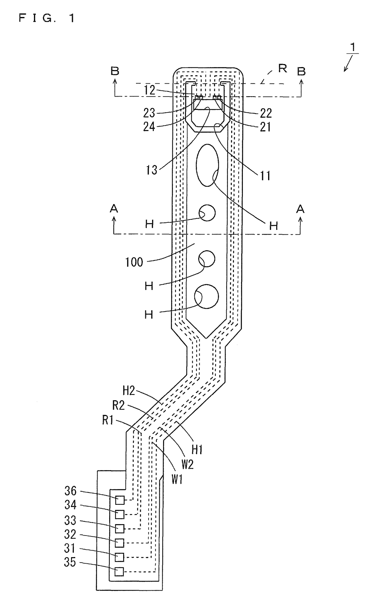
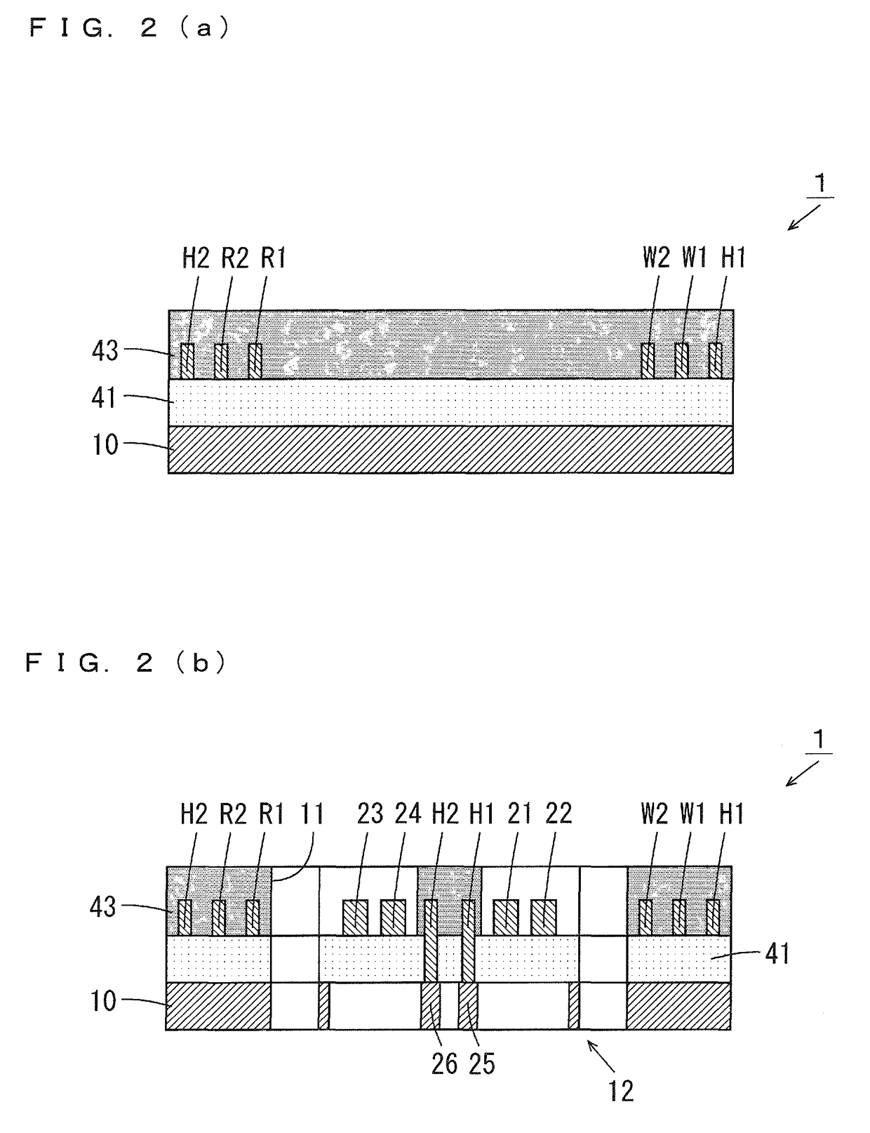
[0055](1) Configuration of Suspension Board

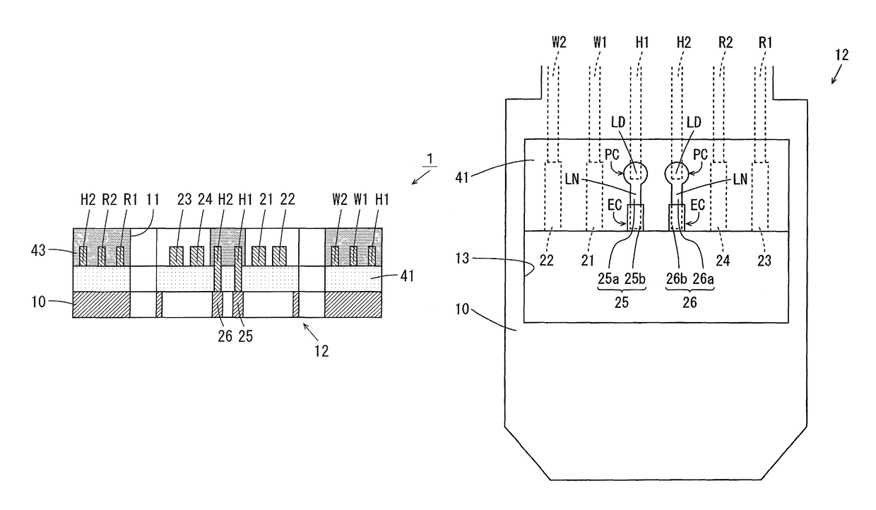
[0056]FIG. 1 is a top view of the suspension board according to the first embodiment of the present invention. As shown in FIG. 1, the suspension board 1 includes a suspension body 100 formed of a metallic long-sized support substrate. As indicated by the dotted lines, write wiring traces W1, W2, the read wiring traces R1, R2 and heat-assisted wiring traces H1, H2 are formed at the upper surface of the suspension body 100.

[0057]At the tip end of the suspension body 100, a magnetic head supporting portion (hereinafter referred to as a tongue) 12 is provided b...

second embodiment

[0095][2] Second Embodiment

[0096](1) Configuration of Connection Terminals

[0097]With regard to the suspension board 1 according to the second embodiment, difference from the suspension board 1 according to the first embodiment will be described. The configuration of the suspension board 1 according to the second embodiment is similar to the configuration of the suspension board 1 according to the first embodiment except for the configuration of the connection terminals 25, 26.

[0098]FIG. 7 is a bottom view of the tongue 12 of the suspension board 1 according to the second embodiment and its peripheral portions. As shown in FIG. 7, in the present embodiment, the metal layer 25b is formed to cover the entire land portion and the straight line portion of the insular portion 25a. Similarly, the metal layer 26b is formed to cover the entire land portion and the straight line portion of the insular portion 26a.

[0099]Each of the connection terminals 25, 26 has a narrow portion NP formed be...

third embodiment

[0109][3] Third Embodiment

[0110](1) Configuration of Connection Terminals

[0111]With regard to the suspension board 1 according to the third embodiment, difference from the suspension board 1 according to the first embodiment will be described. The configuration of the suspension board 1 according to the third embodiment is similar to the configuration of the suspension board 1 according to the first embodiment except for the configuration of the connection terminals 25, 26.

[0112]FIG. 10 is a bottom view of the tongue 12 of the suspension board 1 according to the third embodiment and its peripheral portions. As shown in FIG. 10, in the present embodiment, each of the insular portions 25a, 26a has a wide portion at the end of each of the straight line portions opposite to the land portion. The metal layer 25b is formed to cover the entire land portion, the straight line portion and the wide portion of the insular portion 25a. Similarly, the metal layer 26b is formed to cover the entir...


PUM

PropertyMeasurementUnit
thicknessaaaaaaaaaa
thicknessaaaaaaaaaa
thicknessaaaaaaaaaa

Abstract

Heat-assisted wiring traces and a conductive support substrate are respectively formed on first and second surfaces of an insulating layer. Further, connection terminals electrically insulated from the support substrate and electrically respectively connected to the heat-assisted wiring traces are formed on the second surface of the insulating layer. Each connection terminal has an element connection portion, a pattern connection portion and a spread blocking portion. When a circuit element is connected to the element connection portion of the connection terminal by solder, spreading of a molten solder applied to the element connection portion to the pattern connection portion is blocked by the spread blocking portion.

Description

BACKGROUND OF THE INVENTION[0001]Field of the Invention[0002]The present invention relates to a suspension board with a circuit and a method of manufacturing the same.[0003]Description of Related Art[0004]Actuators are used in drives such as hard disc drives. Such an actuator includes an arm provided rotatably around a rotation shaft, and a suspension board with a circuit for a magnetic head that is attached to the arm. The suspension board with a circuit is a printed circuit board for positioning the magnetic head at a desired track of a magnetic disc.[0005]Generally, in the suspension board with a circuit, a wiring and a connection terminal are formed at one surface and a metal substrate is formed at another surface, of an insulating layer. In a suspension described in JP 2012-119032 A, a plurality of conductors and a plurality of connection terminals are formed at the upper surface of the insulating layer, and a metal base is formed at the lower surface of the insulating layer. A...

Claims


Application Information

Patent Timeline
Patent Type & Authority Patents(United States)
IPC IPC(8): H05K1/00H05K3/34G11B21/16G11B5/48H05K1/09H05K1/03
CPCH05K3/3405G11B5/4853H05K2201/09427H05K2201/09727H05K2203/046Y10T29/49147
Inventor IHARA, TERUKAZUTERADA, NAOHIRO
Owner NITTO DENKO CORP
Why Eureka
Try Eureka