Removal device for micro-bubbles and dirt particles

a technology for dirt particles and removal devices, which is applied in liquid degasification, heating types, separation processes, etc., can solve the problems of high manufacturing cost, disadvantageous form of ep0244881a1, and flow in the removal device according to the flow pattern

Active Publication Date: 2017-09-19
FLAMCO BV
View PDF22 Cites 1 Cited by
  • Summary
  • Abstract
  • Description
  • Claims
  • Application Information

AI Technical Summary

Benefits of technology

[0013]With the present invention, the incoming main flow is more evenly distributed over the width of the housing. The curved plates urge a part of the main flow sideways, to the left and right sides of the housing. This results in a more effective gas and dirt removal.
[0049]This arrangement further improves the use of the available volume within the housing.

Problems solved by technology

It was found that the flow in the removal device according to FIG. 1 of EP0244881A1 has a disadvantageous form.
Further, the longitudinal baffles 2 are complex and lead to high manufacturing costs.
Furthermore, it was found that the removal device according to FIG. 1 of EP0244881A1 is limited in terms of installation capabilities.
The removal device of EP0244881A1 is in particular less suitable for smaller houses and buildings, wherein a heating system generally has limited piping in horizontal direction.

Method used


Image

  • Removal device for micro-bubbles and dirt particles
  • Removal device for micro-bubbles and dirt particles
  • Removal device for micro-bubbles and dirt particles

Examples


Embodiment Construction

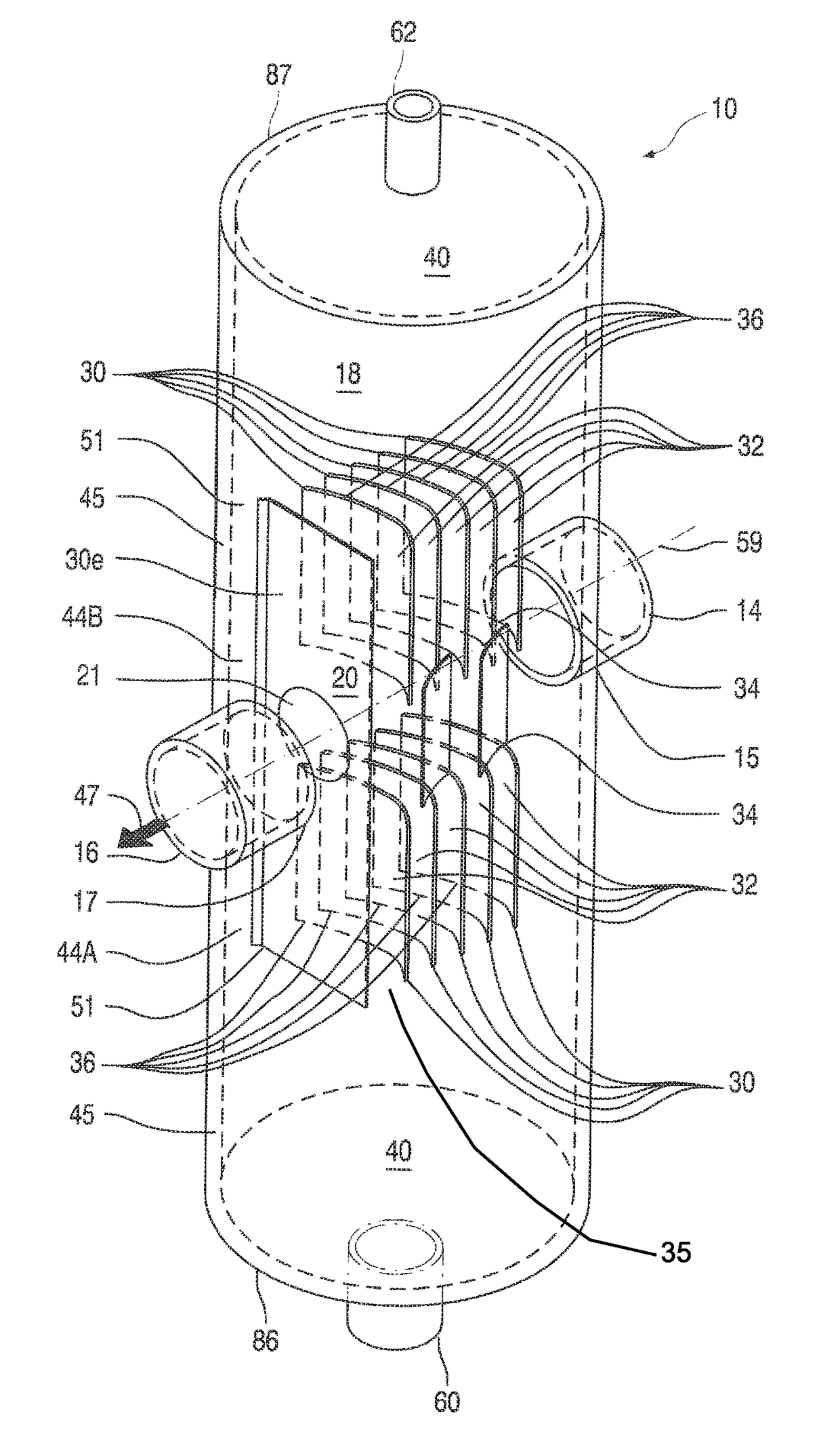
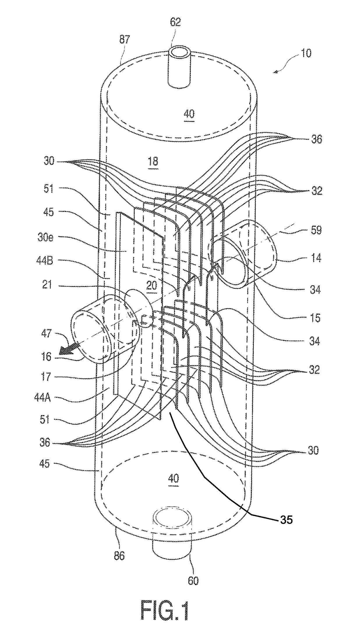
[0082]Turning to FIG. 1, a dirt and gas removal device 10 according to the invention is shown. The dirt removal device 10 comprises a housing 12, an entry 14 and an exit 16. The housing 12 defines an inner space 18. In this embodiment, the housing is circular when seen in top view. Other forms of the housing are possible, such as an oval or square form or other form. In top view, a wall 13 forms a circumferential wall of the housing 12.

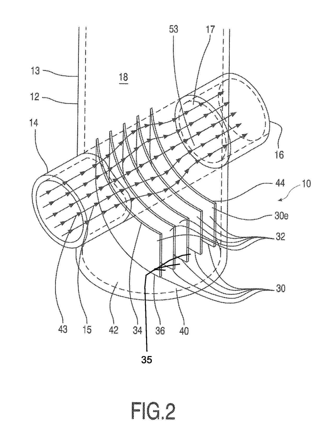
[0083]The entry 14 comprises a short length of pipe which ends at the housing 12 and defines an entry opening 15 in the housing. The exit 16 also comprises a short length of pipe which ends at the housing and defines an exit opening 17 in the housing. The entry 14 and exit 16 have couplings such as thread which allow connection to a liquid conduit system, such as a heating system. Other kinds of couplings which are known in the field are also possible.

[0084]A main flow channel 20 is defined between the entry opening 15 and the exit opening 17. The mai...


PUM

PropertyMeasurementUnit
velocityaaaaaaaaaa
widthaaaaaaaaaa
angleaaaaaaaaaa

Abstract

A removal device for removing gas bubbles and / or dirt particles from a liquid in a liquid conduit system includes a housing having an entry and an exit and, a main ongoing flow channel which extends through the housing from the entry to the exit, a plurality of branch flow channels, each branch flow channel branching off from the main flow channel at a branch point, at least one quiet zone which is provided at the ends of the branch flow channels, at least one return flow channel for a return flow from the at least one quiet zone back to the main flow channel, where the return flow channel merges with the main flow channel at a merge point, and where the branch flow channels are defined by plates which are curved.

Description

CROSS-REFERENCE TO RELATED APPLICATIONS[0001]This application is the National Stage of International Application No. PCT / NL2012 / 050092, filed Feb. 17, 2012, which claims the benefit of Netherlands Application Nos. NL 2006225, filed Feb. 17, 2011, NL 2006226, filed Feb. 17, 2011, and NL 2006227, filed Feb. 17, 2011, the contents of all of which is incorporated by reference herein.FIELD OF THE INVENTION[0002]The present invention relates to a removal device for gas micro-bubbles and dirt particles from a liquid in a liquid conduit system. Removal devices are known. The present invention further relates to an improved hydraulic separator.PRIOR ART[0003]In the prior art, various removal devices for dirt particles and gas micro-bubbles have been developed. EP0244881A1 discloses a removal device with ongoing flow channels 3, see FIG. 1 of EP0244881A1. The flow channels 3 are defined by longitudinal baffles 2 which are inclined. At the upper end and lower end of the flow channels 3, latera...

Claims


Application Information

Patent Timeline
Patent Type & Authority Patents(United States)
IPC IPC(8): B01D21/00B01D17/02B01D19/00B01D21/24F24D19/00
CPCB01D21/0042B01D17/0211B01D19/0042B01D21/0045B01D21/245B01D21/2494F24D19/0092
Inventor CNOSSEN, JAN HENKDEVLIN, TERENCE ARTHUR
Owner FLAMCO BV
Why Eureka
Try Eureka